


PANDUIT® DPoE™ Power Patch Panel User’s Guide Issue 2.2
Part Number: PN378A
14
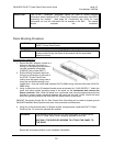
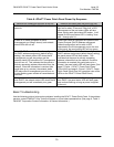
WARNING:
The power supply connections are polarized.
The DPoE™ Power Panel will not function if power is wired improperly.
For Maximum power the overall length of the wire between the power
supply and the DPoE™ Power Panel must not exceed 35 feet.
NOTE:
The included power harness has two wires for the A-feed power only (pins
1 & 2). The DPoE™ Power Patch Panel supports an optional redundant
B-feed power option, but the terminals and wire leads are not attached to
the power harness.
Contact PANDUIT Technical Support for more information about
connecting the redundant B-Feed Power.
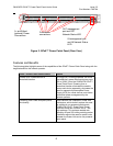
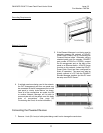
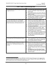
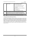
14. Lightly tug on the butt spliced connections to verify that the butt splices are secure.
Powering Up the DPoE™ Power Patch Panel
15. Plug the connector into the back of the DPoE™ Patch
Panel.
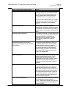
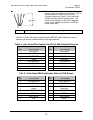
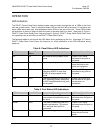
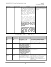
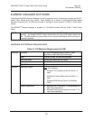
16. Once power is applied to the unit, the DPoE™ Power Patch
Panel will go through its power up sequence. The following
table describes the behavior of the unit as viewed from the
front and the back.