1. Installation
2600-A2-GN20-10 January 2004
1-3
Cables Required
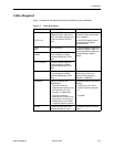
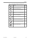
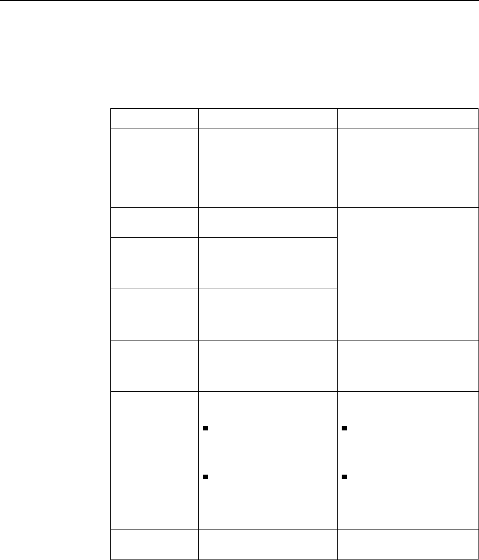
Ta bl e 1-2 shows all the cables that may be required for your installation.
Table 1-2. Cable Descriptions
Connector Name Connector and Cable For Connecting . . .
DSL PORTS 1–24
POTS 1–24
50-pin RJ21X Telco-type
straight connector and 50-wire
cable. Two cables required, one
for DSL and one for POTS (if
used).
Up to 24 DSL ports to Main
Distribution Frame, punchdown
block, or splitters.
Up to 24 POTS splitter ports to
Main Distribution Frame or
punchdown block.
Port 3
GigE
SFP Transceiver An upstream BitStorm 2600 to a
downstream BitStorm 2600, or a
downstream BitStorm 2600 to an
upstream BitStorm 2600 or
network.
Port 3
1000BT
8-position modular plug and
8-wire Category 5 or better
unshielded twisted pair (UTP)
cable.
Port 2 10/100BT 8-position modular plug and
8-wire Category 5 or better
unshielded twisted pair (UTP)
cable.
Port 1 10/100BT 8-position modular plug and
8-wire Category 5 or better
unshielded twisted pair (UTP)
cable.
A Network Management System
(NMS) over a Local Area
Network (LAN) employing
10BaseT or 100BaseT.
CONSOLE DB9 plug connector and
shielded cable.
The other connector
depends on the serial port on
your terminal or PC, but
normally is a DB9 socket.
The other connector
depends on the serial port on
your modem, but normally is
a DB25 plug. A null modem
(crossover) cable is required.
The BitStorm 2600 to one of the
following:
A terminal or a PC with a
terminal emulation program,
or
A modem.
ALARM 5-position terminal block and
shielded, twisted-pair cable.
The BitStorm 2600 to an alarm
system.


