3. LEDs
3-2 January 2004 2600-A2-GN20-10
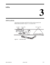
LED Meanings
When power is first applied to the unit, it performs a power-on self-test. When this
test is successfully completed, the Status LED blinks. The meaning of all the LEDs
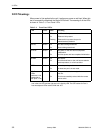
is shown in Table 3-1, Front Panel LEDs.
Table 3-1. Front Panel LEDs
LED Color State Meaning
Link*
* The three RJ45-type connectors for Port 1, Port 2, and Port 3 bear two LEDs: the left
one is the Link LED and the right one is the Activity LED. The SFP socket for Port 3
has two adjacent LEDs marked LINK and ACT.
Green Off
On
Flashing
No Ethernet link present.
Ethernet Link present.
Ethernet link is present, but port is
administratively disabled.
Activity* Green Off
On
No data is being transferred.
Data is being transferred.
STATUS Green Off
On
No power, or the unit has not completed
initialization.
Unit has power and has completed initialization.
ALARM Amber Off
On
No Alarms.
Unit failed self-test, or the unit has exceeded a
safe temperature, or a fan has failed.
TEST Amber Off
On
Normal operating mode.
At least one port is in test mode.
DSL Ports
(LEDs
numbered 1–24
correspond to
DSL ports 1–24)
Green Off
On
The port is disabled or no signal is detected on
the line.
Port has successfully trained with the remote
and is active.


