


2600-A2-GN20-10 January 2004 3-1
3
LEDs
LED Locations
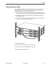
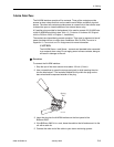
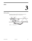
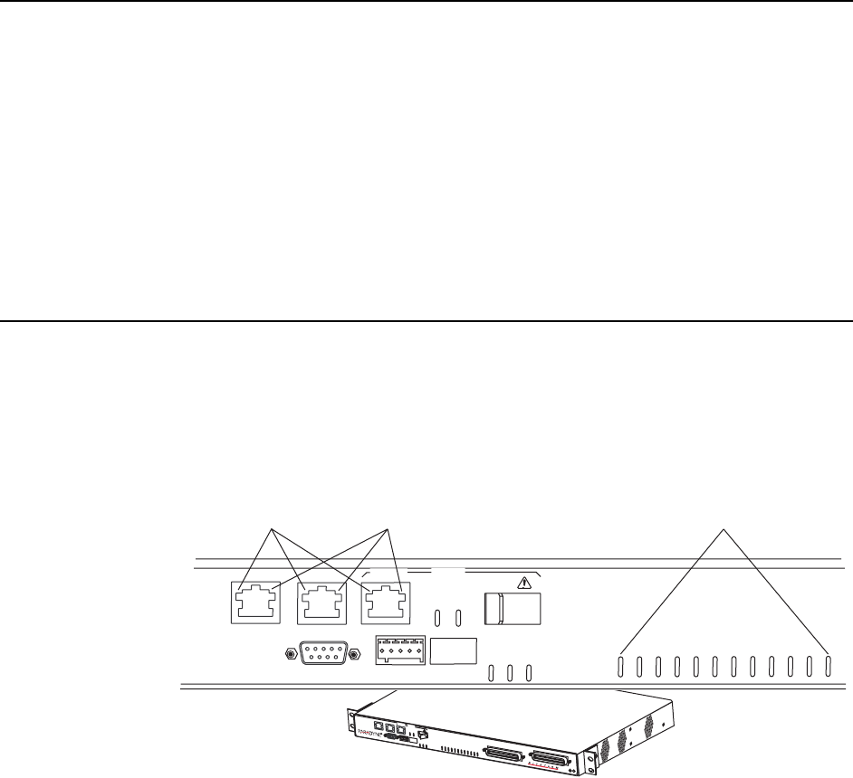
The locations of the System and DSL Port LEDs on the front panel of the
BitStorm 2600 are shown in Figure 3-1, Front Panel LEDs.
Figure 3-1. Front Panel LEDs
03-17454
PORT1-10/100BT
CONSOLE
PORT2-10/100BT PORT3
LINK
ACT
GigE
STATUS
ALARM
TEST
ALARM
1
2
23
1000BT
24
3
4
5
6
7
8
9
10
11
12
13
14
15
16
17
18
19
20
21
22
Link LEDs Activity LEDS DSL Ports LEDs
2
6
0
0
P
O
R
T
1
-
1
0
/
1
0
0
B
T
C
O
N
S
O
L
E
P
O
R
T
2
-
1
0
/
1
0
0
B
T
P
O
R
T
3
L
I
N
K
A
C
T
G
i
g
E
S
T
A
T
U
S
A
L
A
R
M
T
E
S
T
A
L
A
R
M
1
2
2
3
D
S
L
P
O
R
T
S
1
-
2
4
1
0
0
0
B
T
2
4
3
4
5
6
7
8
9
1
0
1
1
1
2
1
3
1
4
1
5
1
6
1
7
1
8
1
9
2
0
2
1
2
2
P
O
T
S
1
-
2
4