


7. Monitoring and Troubleshooting
7-6
March 2001 3160-A2-GB24-10
Performance Reports
When the network interface is configured for ESF operation, network performance
is continuously monitored and maintained in two sets of aggregate registers:
Carrier Network Interface Registers (Telco), and
User Network Interface Registers (User).
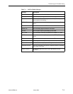
The User registers contain an extra status register (Status Event). Registers
shown on the front panel LCD are listed in Table 7-3, Performance Registers.
These registers are status registers that collect performance data for the previous
24-hour period. Performance data is updated in 15-minute intervals. After
15 minutes, the current interval is rolled over into a set of accumulator registers
that represent the previous 96 15-minute intervals for the register. An interval total
of how many of the 96 registers contain valid data is also kept, as well as a
24-hour total for each accumulator register.
Port performance is continuously monitored and maintained in memory registers
when the port is configured to use EDL. The DSU/CSU maintains two sets of port
registers for each synchronous data port:
far-end port registers, and
near-end port registers.
These registers are status registers that collect performance data for the previous
8-hour period. Port data is updated in 15-minute intervals. After 15 minutes, the
current interval is rolled over into a set of accumulator registers that represent the
previous 32 15-minute intervals for the register. An interval total of how many of
the 32 registers contain valid data is also kept, as well as a 8-hour total for each
accumulator register.
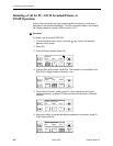
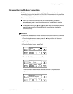
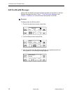
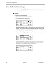
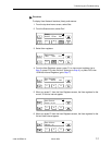
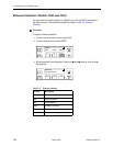
NOTE:
The following procedure is an example only.
Screen displays may vary
depending on the model and configuration of the DSU/CSU.
The
procedures for displaying Telco and port registers are similar to this example.
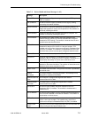
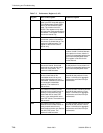
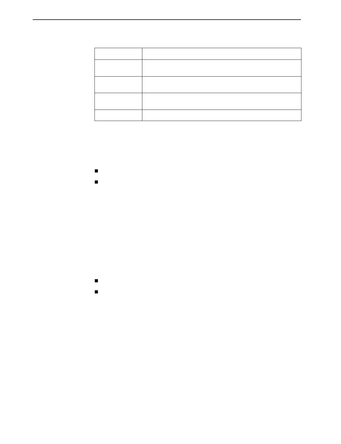
Selftest failed A failure was detected during the power-on self-test. Select STest (in
the Stat branch) to display more information about the failure.
System
Operational
This message only appears if there are no valid alarm or status
messages.
Yellow at DTE A Yellow Alarm signal is being received by the DTE Drop/Insert
(DSX-1) interface.
Yellow at Network A Yellow Alarm signal is being received by the network interface.
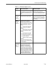
Table 7-2. Device Health and Status Messages (2 of 2)
Message Description