2. Hotwire Menus and Screens
2-14
April 2001 8000-A2-GB26-50
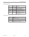
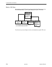
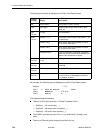
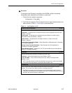
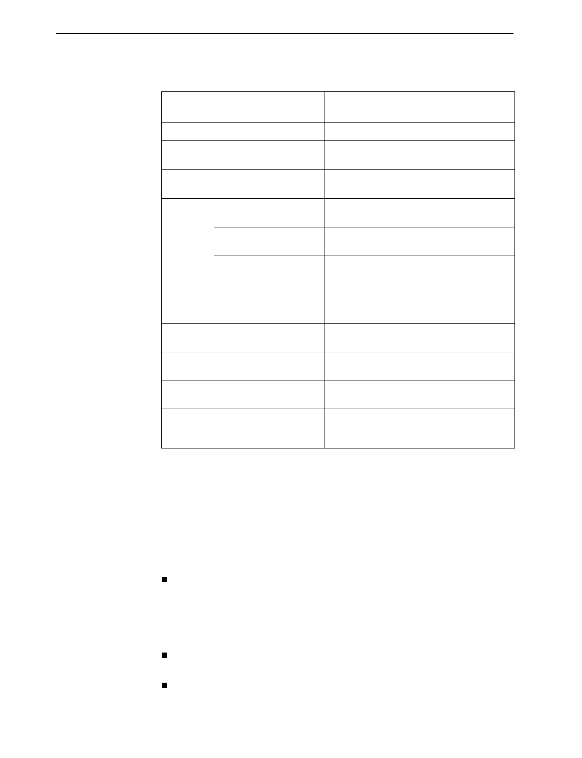
The following information is displayed on the Port Card Select screen.
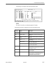
For example, the following may be displayed on the Port Card Select screen:
Position:
1
2
3
Line 1:
1: 8510 PC Status _ _ _ 10bT
Line 2:
RADSL(4) U D D D
Line 3:
Eth(1) U
This display shows the following:
There is an 8510 port card with a 10 BaseT interface in Slot 1
— Position 1 – No current test ( _ )
— Position 2 – No major alarm is present ( _ )
— Position 3 – No minor alarm present ( _ )
This RADSL card has four ports. Port 1 is up, while Ports 2 through 4 are
down.
There is an Ethernet uplink (one port) and the link is up.
Column
Heading Display Description
Slot <slot number> Slot number of card in chassis.
Card <card type> Model number of card such as 8510, 8312,
8343, etc.
Typ e
(1st line)
PC Stat Port card status.
Status
(1st line)
Position 1: T or _ Test mode. Card currently in test mode or _ for
no active test.
Position 2: M or _ Major alarm. Major alarm present on card or _
for no active major alarm.
Position 3: R or _ Minor alarm. Minor alarm present on card or _
for no minor alarm active.
<descriptive text> Up to 42 characters of additional information
about the card (IP Conservative software) and
status of the card (Active or Spare).
Typ e
(2nd line)
RADSL, MVL, SDSL, etc.
(1–24)
DSL type (number of ports).
Status
(2nd line)
<port status> Port status: U=Up, D=Down, X=Disabled/Not
Initialized
Typ e
(3rd line)
Eth, etc. (1) Uplink type (number of ports).
Status
(3rd line)
<uplink status> Status of uplink:
U=Up, D=Down, X=Disabled/Not Initialized,
L=Loopback, A=Alarm


