3. DSL Card Configuration
3-14
April 2001 8000-A2-GB26-50
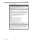
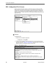
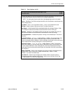
IDSL Ports (DSL Parameters) 8303 IDSL Card A-B-B
8304 IDSL Card A-B-A
Allows configuration of the operational and alarm parameters of the IDSL ports on the
IDSL 8303/8304 cards. Each IDSL port is configured separately.
NOTE: For other types of port cards, refer to the appropriate section in this table.
Action
– Edit to configure DSL ports. Reset to reset port and activate changes.
Port Name
– Enter 1–24.
State
– Port state. This field is read-only. Displays Port Enabled, Port Not Enabled (port is
performing a reset, or has never been made active), or Port Not Selected (a port number
has not been specified for display). (Default = Port Not Selected).
SN Type
– Model number of the service node (Default = 6301R2). For Model 8303/8304
IDSL cards, SN type is Paradyne 6301R2, Paradyne 6302R2, or None (R2 indicates
Release 2 or greater). Select None when the port is connected to a network timing source
only and no endpoint is attached. Use Ctrl-v for a pop-up menu with available selections.
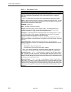
Line Code
– 2B1Q. (This field is read-only.)
Data Rate
–
144/128/64 (Default = 144 kbps).
Link Encapsulation
– Determines the protocol to be run on the selected port
(Default = EtherHDLC). Use Ctrl-v for a pop-up menu with available selections. Choose
from the following:
– EtherHDLC for IP packet applications
– FUNI/MPOA for 8304 cards only
NOTE: If you select FUNI/MPOA, the endpoint must be configured for routing only,
otherwise the line will fail to come up and a SYSLOG message will be generated.
Channel for 64 Kbps
–
B1/B2 (Default = B1). Valid channel for 64 kbps operation.
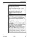
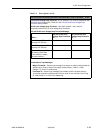
Transceiver Mode
–
Enter NT (Network Termination) or LT (Line Termination)
(Default = LT). NT is used for timing while LT is used for data. One and only one IDSL port
in each chassis must be dedicated as NT and connected to the appropriate ISDN timing
source in the CO. This timing is then distributed to all other IDSL ports in the chassis.
Only the first four ports on the card can be set to NT.
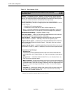
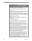
For timing: An IDSL circuit must be synchronized with the Digital Carrier System (the
Digital Loop Carrier or DLC). The port you select for NT mode will be used to terminate a
connection to an LT dedicated for system clock use. This NT port will probably not be
used for data, but will derive the 2.048 Mhz system clock from the connection and
distribute this timing to the other 23 IDSL ports on this card, and to other IDSL port cards
via the backplane clock circuit. Once you have set one of the ports on the IDSL card for
NT mode, use the IDSL Clock Configuration screen (
A-G-B
) on the MCP card to
configure one of the clock circuits on the backplane to receive its timing from the IDSL
port you just configured. To do this, set the Clock Configuration for
NET_CLOCK1/NET_CLOCK2 field to 3 for Drive System Clock).
NOTE: If the NT port loses the connection and the timing source fails, all IDSL loops
on the chassis may lose data (denoted by Major Alarm and SNMP trap). For
redundancy, you may wish to dedicate an additional port on another IDSL card in the
chassis as a spare timing source and leave the port it in LT mode. In case of failure,
this secondary timing port can be enabled remotely by changing the status of the
primary timing port to LT and the secondary port to NT. Be aware that the
NET_CLOCK1 and NET_CLOCK2 options must be configured correctly on the MCC
card. See the
Hotwire Management Communications Controller (MCC) Card, IP
Conservative, User’s Guide
for more information.
Table 3-2. Ports Options (7 of 9)


