


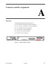
A. Connectors and Pin Assignments
A-2 June 2004 2600-A2-GN20-20
DSL Ports and POTS Splitter Connectors
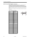
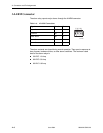
The 50-pin RJ21X Telco connector labeled DSL Ports 1–24 provides the 2-wire
loop interface from each DSL port to the MDF for CO applications, or the
in-building wiring for customer premises applications. (The Canadian designation
for this connector is CA21A.) The 50-pin RJ21X (CA21A) Telco connector labeled
POTS 1–24 (if installed) provides the 2-wire loop interface with the internal POTS
splitters.
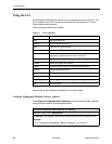
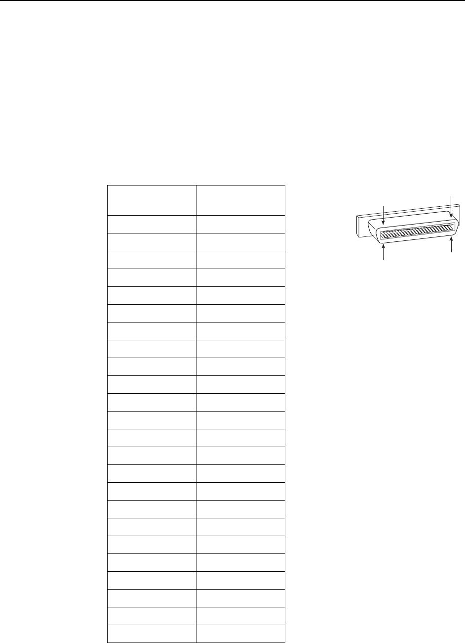
Ta bl e A -1 lists the pin assignments for these interfaces. Note that Pins 25 and 50
are not used.
Table A-1. DSL Connector Pinouts
DSL Port
Connector Pins
(Ring, Tip)
11, 26
22, 27
33, 28
44, 29
55, 30
66, 31
77, 32
88, 33
99, 34
10 10, 35
11 11, 36
12 12, 37
13 13, 38
14 14, 39
15 15, 40
16 16, 41
17 17, 42
18 18, 43
19 19, 44
20 20, 45
21 21, 46
22 22, 47
23 23, 48
24 24, 49
25
02-17151
1
50
26