2. Installation
8620-A2-GN20-40 July 2003
2-15
Procedure
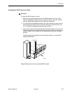
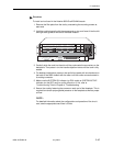
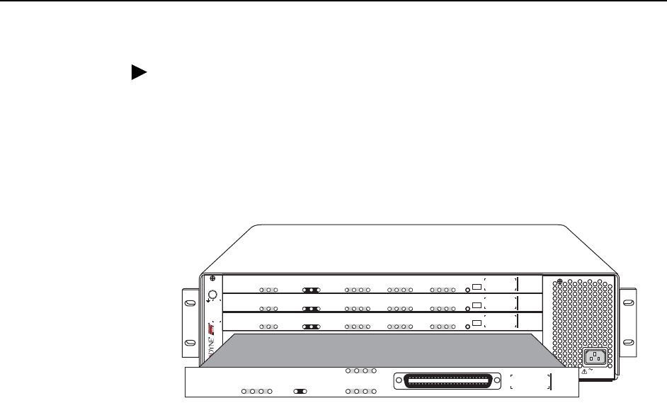
To install a circuit card in the Hotwire 8620 GranDSLAM chassis:
1. Remove the filler plate from the slot by unscrewing the mounting screws at
each end.
2. Hold the card horizontally with the components on top, and insert it into the left
and right card guides of the slot of the base chassis.
3. Carefully slide the card into the slot until the card meets the connectors on the
backplane. Then press in on the insertion/ejection levers until the card is fully
seated.
4. For desktop installations, press on the card’s front panel with one hand and on
the back of the 8620 chassis with the other until the card’s connector seats in
its mating connector.
5. Make sure the SYSTEM OK indicator (on DSL cards) or SYSTEM ACTIVE
indicator (on the SCP card) is cycling off and on. If not, refer to
Troubleshooting Table in Chapter 4, Troubleshooting.
6. Secure the card by fastening the screws on each end of the faceplate. This is
required to maintain proper gasket pressure on the faceplate as well as proper
air flow.
NOTE:
For detailed information about the configuration and operation of the circuit
card, see the appropriate card User’s Guide.
03-17430
GranDSLAM
8620
ESD
SIM
A
1
2
3
AC INPUT
DC FUSES
A
B
-48V RTN
ABAB
AB
DC
POWER
F
A
N
M
A
J
O
R
M
I
N
O
R
ALARMS
ALARM
CLOCK
AB
SERIAL
SCM MCP
LAN
SCM MCP
SIM
SYSTEM
Active
Standby
Alarm
TX
RX
ETHERNET
Test
UPLINK
LK1
LK2
LK3
LK4
LK5
LK6
LK7
LK8
SCP-IMA
8417
G.DMT
G.Lite
8965
SYSTEM
OK
Alrm
Tes t
TX
RX
LOC
1/13
2/14
3/15
4/16
ATM BUS
DSL PORT
5/17
6/18
7/19
8/20
PORT
9/21
10/22
11/23
12/24
PORT
ALT BANK
13-24
1-12
G.DMT
G.Lite
8965
SYSTEM
OK
Alrm
Tes t
TX
RX
LOC
1/13
2/14
3/15
4/16
ATM BUS
DSL PORT
5/17
6/18
7/19
8/20
PORT
9/21
10/22
11/ 23
12/24
PORT
ALT BANK
13-24
1-12
G.DMT
G.Lite
8965
SYSTEM
OK
Alrm
Tes t
TX
RX
LOC
1/13
2/14
3/15
4/16
ATM BUS
DSL PORT
5/17
6/18
7/19
8/20
PORT
9/21
10/22
11/ 23
12/24
PORT
ALT BANK
13-24
1-12


