


2. Installation
2-16 July 2003 8620-A2-GN20-40
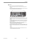
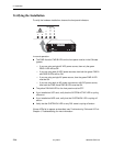
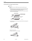
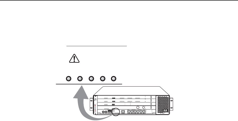
Verifying the Installation
To verify the hardware installation, observe the front panel indicators.
In normal operation:
n The PWR A and/or PWR B LEDs on the front panel must be in the ON state
(green):
— If you are using a single 48 VDC power source, then only the green
PWR A LED will be ON.
— If you are using dual 48 VDC power sources, then both the green PWR A
and PWR B LEDs will be ON.
— If you are using a single AC power source, then the green PWR A LED
must be ON.
— If you are using both an AC power source and a 48 VDC power source,
then both the PWR A and PWR B LEDs must be ON.
n The yellow FAN ALM LED on the front panel must be OFF.
n If you installed an SCP card, verify that the SYSTEM ACTIVE LED is cycling
off and on.
n If you installed an MCP card, verify that the SYSTEM OK LED is cycling off
and on.
n Verify that the SYSTEM OK LED on any DSL cards is cycling off and on.
If these LEDs fail to appear as described, see Troubleshooting Table and LEDs in
Chapter 4, Troubleshooting, for more information.
MCP
8000
SYSTEM
OK
Alrm
Test
TX
RX
Coll
ETHERNET
GranDSLAM
8620
ESD
SIM
A
1
2
3
DC FUSES
A
B
-48V RTN
ABAB
AB
DC
POWER
F
A
N
M
A
J
O
R
M
I
N
O
R
ALARMS
ALARM
CLOCK
AB
SERIAL
SCM MCP
LAN
SCM MCP
SIM
IP
MVL
8314
SYSTEM
OK
Alrm
Tes t
TX
RX
LOC
1
2
3
4
ATM BU S
DSL PORT
5
6
7
8
9
10
11
12
SCM-E3
10/100BT
8025
SYSTEM
OK
Alrm
Test
TX
RX
Coll
ETHERNET
Uplink Alrm
TX
RX
IP
MVL
8314
SYSTEM
OK
Alrm
Tes t
TX
RX
LOC
1
2
3
4
ATM BU S
DSL PORT
5
6
7
8
9
10
11
12
AC INPUT
02-17239
AB
DC
POWER
F
A
N
M
A
J
O
R
M
I
N
O
R
ALARMS