


8620-A2-GN20-40 July 2003 IN-1
Index
A
alarm relay, A-1
ATM, 1-1
ADSL card, 1-3
SDSL card, 1-3
C
cable ties, 3-3
cabling, 2-2, 3-1
alarm, 3-9
computer, 3-5–3-6
modem, 3-7
SNMP, 3-6, 3-8
tip and ring, 3-2
card
ATM ADSL, 1-3
ATM SDSL, 1-3
installing, 2-15
interoperability, 1-4
line, 1-3
MCP, 1-2
SCM, 1-2
SCP, 1-2
CO ground lug, 2-8
components, 1-5
configuration, example, 1-1
cooling and air handling, B-2
D
DLC (Digital Loop Carrier), 1-1
DSL cards, 1-3
F
features, 1-4
G
glossary, Paradyne master, iv
grounding, 2-1, B-2
I
installation
card, 2-14
verification, 2-16
interfaces, B-1
interoperability of line cards, 1-4
ISP (Internet Service Provider), 1-1
L
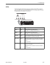
LEDs, 2-16, 4-3
line cards, 1-3
locking pivot bracket, 3-4
M
MCP, 1-2
interoperability, 1-4
mounting configurations, 2-4
attaching the mounting brackets, 2-6
installing in a rack, 2-7
rack mounting, 2-6
N
NAP (Network Access Provider), 1-1
O
operating environment, B-2
P
package contents, 2-3
associated hardware, 2-3
physical dimensions, B-1
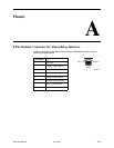
pinouts, A-1
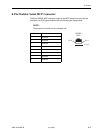
50-pin Telco connector for DSL loops and POTS
splitters, A-5
8-pin modular
connector for alarm relay, A-1
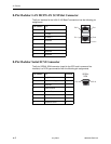
connector for LAN slot connector, A-2
serial connector, A-2–A-3
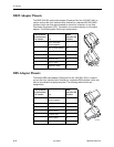
DB25 adapter, A-4
DB9 adapter, A-4
port cards, 1-3
power, 1-4, 2-1, 2-9, B-1
AC, 2-12
AC with DC backup, 2-13
DC, 2-10
redundant DC, 2-11
preinstallation, 2-1