4. DSL Router Configuration Examples
4-14 November 2003 6300-A2-GB20-10
Downstream Router Configuration Example
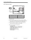
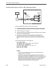
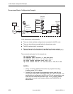
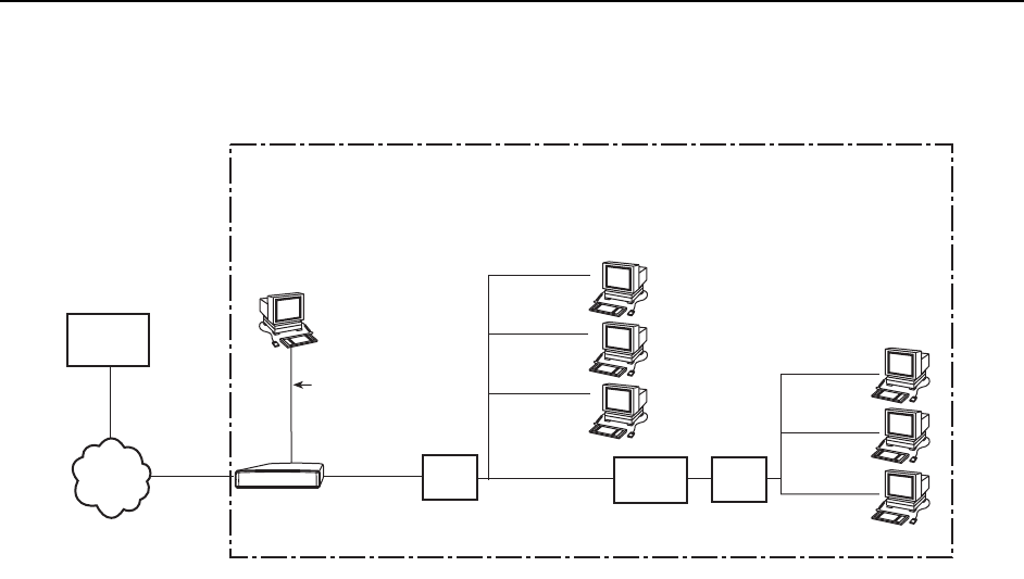
In this downstream router example:
There are clients statically configured and connected to the DSL router.
There are also clients connected behind a downstream router.
The DSL interface (dsl1) is numbered.
The next hop router for downstream forwarding from the core router to
networks 120.26.7.0 and 130.26.7.0 is the DSL router’s DSL interface (dsl1).
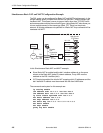
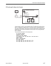
The commands and syntax for this example are:
ip routing enable
ifn address eth1 120.26.7.5 255.255.255.0
ifn address dsl1 155.1.3.2 255.255.255.0
ip route create upstream eth1 155.1.3.1
ip route create 130.26.7.0 255.255.255.0 120.26.7.100
NOTES:
— The ip routing enable command is only required when using
firmware version 4.2.5 or higher.
— FUNI/MPOA (1483 routed) link encapsulation can be used with this
configuration and the DSL card Models 8304, 8314, 8344, and 8374. Link
encapsulation is configured on the DSL port. This link encapsulation must
match the core network encapsulation type. The ip route create
upstream command is not necessary when using FUNI/MPOA link
encapsulation.
00-16591-01
Customer Premises (CP)
End-user
Systems
Router
Hub
End-user
Systems
120.26.7.1
120.26.7.2
120.26.7.3
120.26.7.100
130.26.7.1
130.26.7.2
130.26.7.3
DSL
Router
Hub
Console
Port
Connection
DSL
Core
Router
dsl1
155.1.3.2
WAN
155.1.3.1
eth1
120.26.7.5
Ethernet


