


13
4.0 INSTALLATION
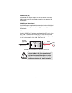
Once the Model 1088 is properly configured, it is ready to connect to the
twisted pair interface, to the serial port, and to the power source. This
section tells you how to make these connections.
4.1 CONNECTING THE TWISTED PAIR INTERFACE
The Model 1088 supports communication between two DTE devices at
distances to 5 miles (8 km) over 24 AWG (.5 mm) twisted pair wire. Two
things are essential:
1. These units work in pairs. Both units at the end of the twisted pair
DSL span must be set for the same DTE rate.
2. To function properly, the Model 1088 needs one twisted pair of
metallic wire. This twisted pair must be unconditioned, dry, metallic
wire, between 19 (.9mm) and 26 AWG (.4mm) (the higher number
gauges will limit distance). Standard dial-up telephone circuits, or
leased circuits that run through signal equalization equipment, or
standard, flat modular telephone type cable, are not acceptable.
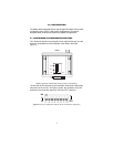
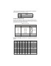
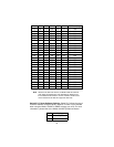
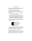
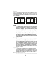
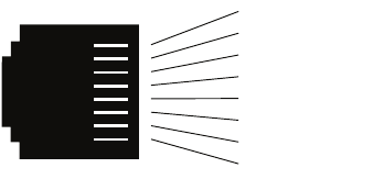
The RJ-45 connector on the Model 1088’s twisted pair interface is polar-
ity insensitive and is wired for a two-wire interface. The signal/pin rela-
tionships are shown in Figure 4.
Figure 4.
Model 1088 RJ-45 twisted pair line interface.
4.2 CONNECTING THE MODEL 1088/C (V.35) SERIAL INTERFACE
Model 1088/C supports V.35 serial port connections. This section
describes how to connect the serial ports to your V.35 equipment.
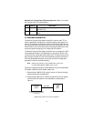
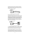
Connecting the Model 1088/C (V.35) to a “DTE” Device
The Model 1088/C provides a V.35 DCE (Data Circuit Terminating Equip-
ment) interface on an M/34 female connector. As a DCE, this interface is
designed to connect to DTE equipment, such as a router. When connect-
ing the V.35 interface of the Model 1088/C to your DTE device, use a
1 (N/C)
2 (N/C)
3 (N/C)
4 (2-Wire TIP)
5 (2-Wire RING)
6 (N/C)
7 (N/C)
8 (N/C)
1
2
3
4
5
6
7
8