


23
data presented at the far end DTE will be transmitted to the
local DTE and then looped back within the local DTE Loop Con-
trol block with the Processor. After the Local Loop is deselected,
the units will be placed back into DataMode and the normal
data paths will be re-established.
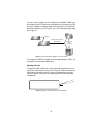
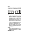
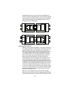
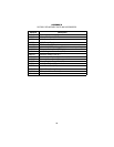
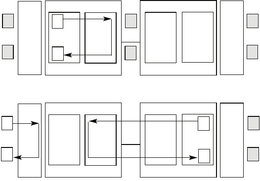
Figure 16.
Block Diagram Local Loop Mode 1 with 511/511E
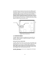
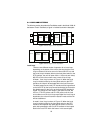
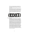
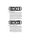
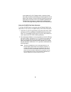
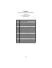
Figure 17.
Block Diagram Local Loop Mode 2 with 511/511E
Local Loop with 511/511E
When the unit is placed into a Mode 1. Local Loop and the 511/
511E pattern generator is activated, the local pattern generator
begins sending out a 511/511E pattern to the Loop Control
block. The Loop Control block will loop this data back to the 511/
511E pattern detector block, which will evaluate the data for
errors. Because the 511/511E pattern generator is contained
within the Processor the data is unframed so the framer will
begin seeing unframed packets. The framer receives this
unframed data and can not distinguish this information from a
line disconnection (this would cause the units' Restart proce-
dure to start). What we have done to allow this mode to work is
to add time outs for the pattern generators. When the 511/511E
is initiated, the line restart procedure is changed to one minute.
The 511/511E pattern will timeout after 45 seconds. So if the
511/511E is turned on during a local loop, the restart procedure
is set to one minute, but the 511/511E pattern will time out after
45 seconds, allowing the framer to begin seeing framed pack-
ets (and not restart the box).
After the 511/511E pattern times out, the ER led will begin
flashing. It will remain this way until the pattern generator switch
is turned off. Note that the data at the local DTE and the remote
Pattern
Gen/Det
Loop
Contr
ol
Loop
Contro
l
Pattern
Gen/Det
Processor
Processor
Framer
Framer
Line
Pattern
Gen/Det
Loop
Contr
ol
Loop
Contro
l
Pattern
Gen/Det
Processor
Processor
Framer
Framer
Line