


22
5.4 LOOPS AND PATTERNS
The following section describes the Test Modes used in the Model 1088. At
the bottom of each Test Mode, a figure is included to show the data path..
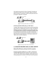
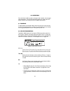
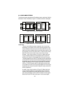
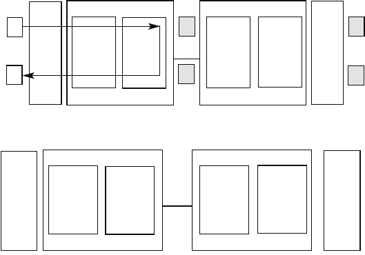
Figure 14.
Block Diagram Local Loop Mode 1
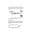
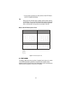
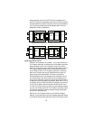
Figure 15.
Block Diagram Local Loop Mode 2
Local Loop
There are two different modes of operation for a Local Loop
depending on the status of the units at the time that the Local
Loop is initiated. If the units are not in linked (NS LED on) and
the Local Loop is initiated, either by the front panel switch or the
DTE interface, the unit will enter mode 1. If the units are linked,
NS LED off, then the unit will enter a mode 2 Local Loop.
A Mode 1 Local Loop is shown in Figure 14. When the Local
Loop is initiated, either by the front panel switch or the DTE
interface, the loop will be activated within the local Processor.
The data present at the local DTE interface will be looped back
to the local DTE by the Loop Control block within the Processor.
Any data present on the line or at the far end DTE interface is
invalid. The remote unit will remain in the StartUP mode, NS
LED on, CTS LED yellow, and CD LED yellow, until the local
unit is taken out of the Local Loop mode. After the Local Loop is
deselected, the units will both be in StartUP mode and the link
will be established.
A mode 2 Local Loop is shown in Figure 15. When the Local
Loop is initiated, either by the front panel switch or the DTE
interface, two separate loop paths will be started. In the first
path, data presented to the local DTE interface will be looped
back to the local DTE within the framer. In the second path,
Pattern
Gen/Det
Loop
Contr
ol
Loop
Contro
l
Pattern
Gen/Det
Processor
Processor
Framer
Framer
Line
Pattern
Gen/Det
Loop
Contr
ol
Loop
Contro
l
Pattern
Gen/Det
Processor
Processor
Framer
Framer
Line