


10
3.2 CONFIGURING THE REAR INTERFACE CARD
Your Model 2073RC comes with one of the following rear cards:
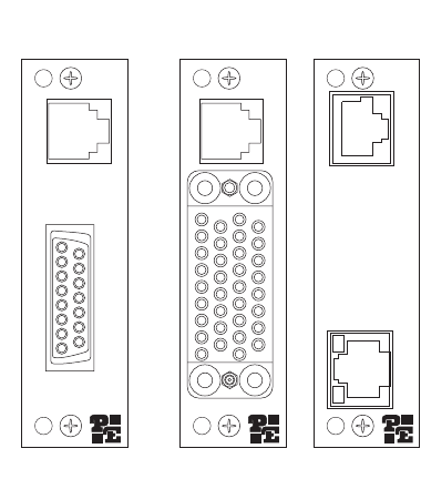
• The Model 1001RCM13448C (M/34/ RJ-48C)
• The Model 1001RCM11548C (DB-15/RJ-48C)
• The Model IM2RC/IA (RJ-45/10Base-T RJ-48C)
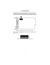
Each of these options supports one DTE interface connection and one 4-
wire line connection. Figure 3 illustrates the interface options for the
Model 2073RC Series.
Note
The 2073RC Series function card is paired with a specially
designed rear card and must not be swapped with other Patton
rear cards.
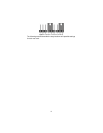
Figure 3.
Model 2073RC Series interface card options
Prior to installation, you will need to examine the rear card and make
sure it is properly configured for your application.
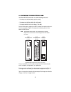
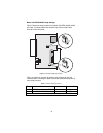
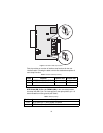
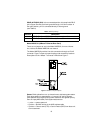
Each rear card is configured by setting straps located on the PC board.
To configure the rear cards, you must set the configuration straps.
Figure 4 shows the orientation of these straps. Each strap can either be
on pegs 1 and 2,or on pegs 2 and 3.
Model
IM2RC/IA
RJ-48C
Model
1001RCM13448C
RJ-48C
M/34 F
Model
1001RCM11548C
RJ-48C
DB-15 F