


14
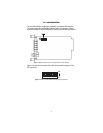
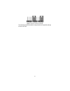
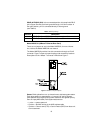
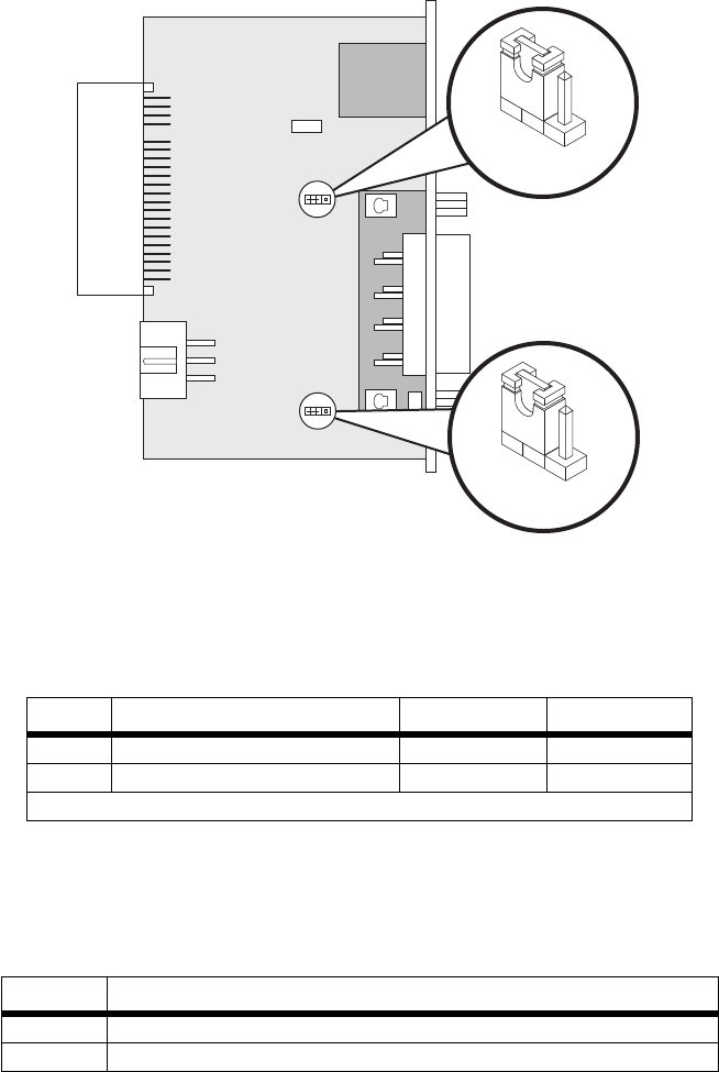
Figure 6.
1001RCM11548C strap locations.
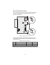
Table 4 provides an overview of interface strap functions for the rear
interface cards. Following the table overview are detailed descriptions of
each strap’s function.
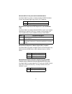
DTE Shield (DB-15 Pin 1) & FRGND (JB3).
In the connected position,
this strap links DB-15 pin 1 & frame ground. In the open position, pin 1 is
disconnected from frame ground (see Table 5).
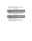
Table 4:
Interface Card Strap Summary
Strap Function Position 1&2 Position 2&3
JB3 DTE Shield (Pin1) & FRGND Connected* Open
JB4 FRGND & SGND (Pin 8) Connected* Open
* Indicates default setting
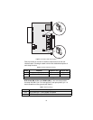
Table 5:
JB3 strap settings
Position Description
1 & 2 DTE Shield (Pin 1) and FRGND Connected
2 & 3 DTE Shield (Pin 1) and FRGND Not Connected
1
3
JB3
123
JB4