


13
5.0 CONFIGURATION
All configuration is done through software auto-detection for the Model
2124/2130. Once you have configured your mux or other equipment to
be connected to the 2124/2130, the unit is ready for operation. Observe
that the serial port of the 2124/2130 is configured as a DTE and must
connect to a DCE.
The LAN port also requires no configuration to connect to a 10BaseT
Ethernet.
Note
The V.24 and EIA-530 Interface is configured as a DTE. The
2124/2130 will transmit and receive data to and from the DCE,
based on the speed of the clocks received from the DCE. On the
LAN side interface, data is sent and received in burst mode at
10Mbps.
5.1 LED STATUS MONITORS
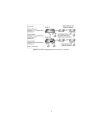
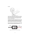
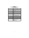
The 2124/2130 uses two LEDs on the Ethernet connection side. A green
LED indicates that link connection to the network is established. The yel-
low LED displays status codes (See section 5.1.2 for status code infor-
mation).
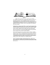
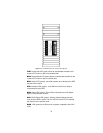
Seven, low power, LEDs located on the top of the 2124/2130 case indi-
cate POWER and V.24 or EIA-530 signal activity.
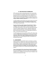
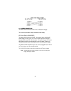
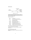
LAN side LEDs
The Model 2124/2130 features two LAN LEDs that monitor general oper-
ation status and the 10BaseT twisted pair link integrity. Figure 8 shows
the LEDs located at the rear of the Model 2124/2130. Following Figure 8
is a description of each LED function. Figure 8 shows the LEDs located
on the top of the Model 2124/2130.