


14
LED Descriptions
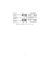
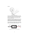
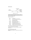
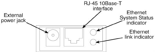
Figure 8.
2124/2130 rear view
The status LED blinks yellow from one to eleven times to indicate system
status. Each pulse pattern is separated by a 2 second "off " period.
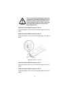
Greater pulse patterns have higher priority (buffer saturation has greater
priority than an empty MAC table).
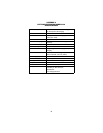
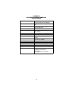
Valid system statuses are:
After a status code is displayed eight times and the associated condition
is removed, the status code will no longer appear.
The link LED glows green to indicate link integrity on the 10BaseT
twisted pair line.
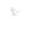
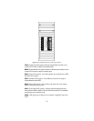
Power and DCE/DTE interface LEDs
Seven LEDs indicate POWER and DTE/DCE activity on the front of the
2124/2130.
1 pulse = system status ok
2 pulses = No MAC entries in the MAC address table
3 pulses = Clear to send (CTS) or Carrier Detect (DCD) from
base unit are not asserted
4 pulses = IMRC2/IA buffer is saturated
5 pulses = WAN receive frame(s) too large
6 pulses = WAN receive frame(s) not Octet aligned
7 pulses = WAN receive frame(s) aborted
8 pulses = Detected WAN receive frame(s) with bad CRC
9 pulses = Detected LAN receive frame(s) too large
10 pulses = Detected LAN receive frame(s) not Octet aligned
11 pulses = Detected LAN receive frame(s) with bad CRC