


11
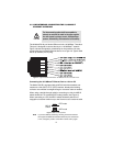
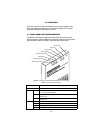
3.2 LINE INTERFACE—CONNECTING THE 10/100BASE-T
ETHERNET INTERFACE
The shielded RJ-45 port labeled
Ethernet
is the 10/100Base-T interface.
This port is designed to connect directly to a 10/100Base-T network.
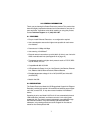
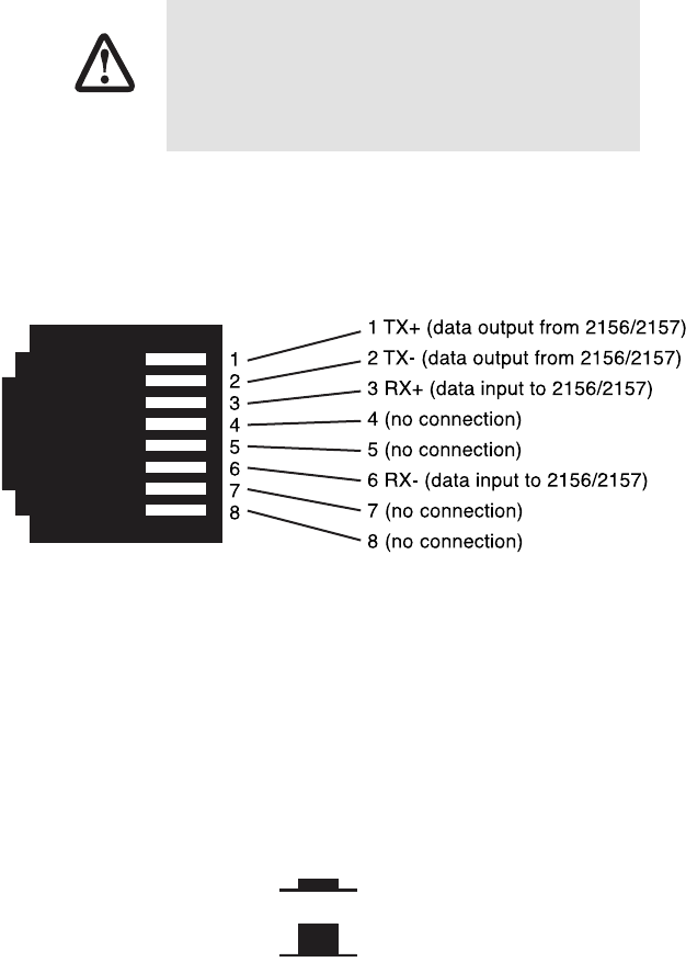
Figure 4 shows the signal/pin relationships on this interface. You may
connect this port to another Ethernet device via a Type 4 or Type 5 cable
that is up to 328 ft (100 m) long.
Figure 4.
CopperLink Ethernet Extender 10/100Base-T RJ-45 Connector Pinout.
Connecting the 10/100Base-T Ethernet Port to a Hub or PC
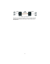
The Model 2157R is equipped with an MDI-X switch that enables con-
nections to a hub (DCE) or PC (DTE) interface, thereby elimininating
confusion over whether a straight-through or crossover cable is needed.
When using a straight-through cable for connecting to a hub, the MDI-X
switch should be in its released (DCE mode) position (see Figure 5).
When connecting to a PC, the MDI-X switch should be pushed in to
engage the crossover function so you won’t have to use a crossover cable
Figure 5.
MDI-X switch positions
Note
If you have difficulty achieving a working connection between
the CopperLink Ethernet Extender’s Ethernet port and the hub
or PC, change the position of the MDI-X switch and try again.
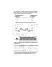
The Interconnecting cables shall be acceptable for
external use and shall be rated for the proper applica-
tion with respect to voltage, current, anticipated tem-
perature, flammability, and mechanical serviceability.
CAUTION
DCE mode
MDI-X
switch
DTE mode