


15
4.0 OPERATION
Once the CopperLink Ethernet Extenders are properly installed, they
should operate transparently. No user settings required. This section
describes reading the LED status monitors.
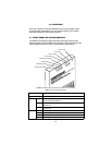
4.1 FRONT PANEL LED STATUS MONITORS
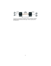
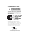
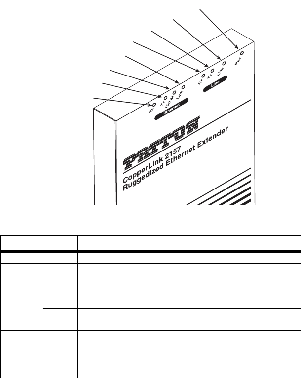
The Model 2157R features eight front-panel LEDs that monitor power,
Ethernet signals, and the CopperLink connection. Figure 9 shows the front
panel location of each LED. Table 1 describes the LED functions.
Figure 9.
CopperLink Ethernet Extender standalone unit front panel
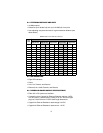
Table 1:
Front panel LED description
LED Description
Power When lit, indicates the unit is powered on
Line Link
•
On solid—link is connected
•
Off—No signal detected
TX Flashing—Data is being transmitted from the local unit to the
remote unit
RX Flashing—Data is being received at the local unit from the
remote unit
Ethernet Link On—Ethernet is linked
100 M On—100 Mbps Ethernet is selected
TX Flashing—When data is transmitted from the unit to the LAN
RX Flashing—When data is received from the LAN
Link LED
Power LED
Link Tx LED
Link Rx LED
Ethernet Link LED
100 M LED
Ethernet Tx LED
Ethernet Rx LED