12
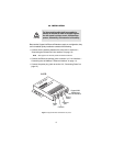
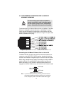
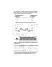
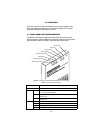
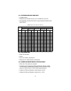
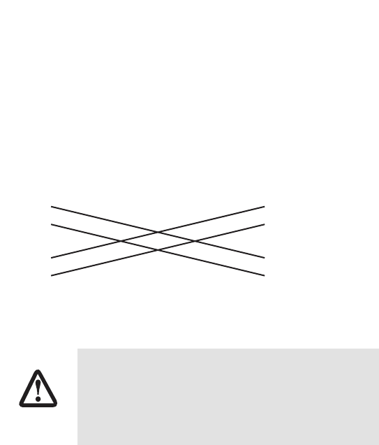
In its released position, the MDI-X switch enables straight-through con-
nections (see Figure 6) or in its inserted position the MDI-X switch per-
forms the crossover function (see Figure 7 on page 12).
Figure 6.
Wiring diagram for connecting the CopperLink Ethernet Extender to a
10/100Base-T hub (MDI-X switch released)
Figure 7.
MDI-X switch pressed in performs 10/100Base-T crossover function
3.3 CONNECTING POWER
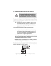
The Model 2157R does not have a power switch, so it powers up as soon
as it is plugged in.
An external AC or DC power supply is available separately. This connec-
tion is made via the barrel jack on the rear panel of the Model 2157R. No
configuration is necessary for the power supply (See Appendix B on
page 19 for domestic and international power supply and cord options).
3.4 POWER INPUT CONNECTOR
The
CopperLink Ethernet Extender comes with an AC or DC power supply.
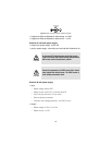
• The supplies connection to the CopperLink Ethernet Extender is a
2.5 mm barrel receptacle with the center conductor positive (see
Figure 6).
The Interconnecting cables shall be acceptable for
external use and shall be rated for the proper applica-
tion with respect to voltage, current, anticipated tem-
perature, flammability, and mechanical serviceability.
2157 10/100Base-T Port
RJ-45 Pin No.
10/100Base-T Hub
RJ-45 Pin No.
1 (TX+)--------------------------------------------------1 (RX+)
2 (TX-)---------------------------------------------------2 (RX-)
3 (RX+)--------------------------------------------------3 (TX+)
6 (RX-)---------------------------------------------------6 (TX-)
2157 10/100Base-T Port
RJ-45 Pin No.
1 (TX+) 1 (TX+)
2 (TX-) 2 (TX-)
3 (RX+) 3 (RX+)
6 (RX-) 6 (RX-)
10/100Base-T DTE
RJ-45 Pin No.
CAUTION


