Model 2292/2294 Quick Start Guide
3
2.
Installing the 10/100 Ethernet port cable or cables
(see
1.4 “Installing the Ethernet cable”
on page 5)
3.
Installing the power input
(see
1.5 “Connecting to external power source”
on page 6)
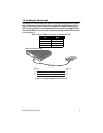
1.3 Installing an interface cable on the extender’s voice ports
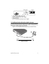
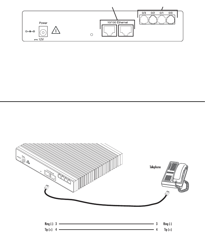
The SmartNode extender comes with at least two voice ports (see
figure 1
) located on the back of the extender.
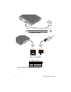
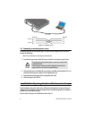
The voice ports are connected to analog devices via cables (see
figure 2
and
figure 3
) terminated with RJ-11 con-
nectors (see
figure 4
and Table 1 on page 4 for pin-out information).
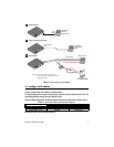
Figure 1.
Rear view showing location of Ethernet connectors and voice ports (SmartNode 2294 shown)
Figure 2.
FXS connection
, 1.25A
Reset
Ports
ETH 0/1 ETH 0/0
Ethernet connectors
Voice ports
RJ-11, male RJ-11, male
, 1.25A
Reset
Ports
ETH 0/1 ETH 0/0


