


14
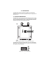
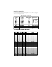
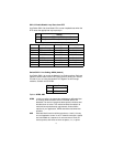
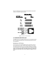
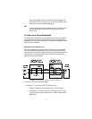
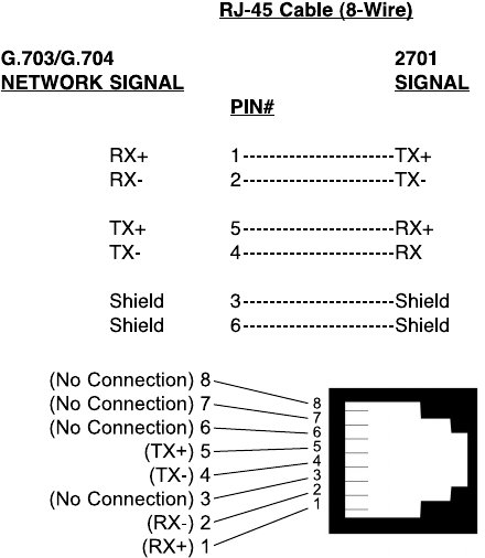
(Figure 4) following the pinout and signals chart below to connect the
120 ohm G.703/G.704 network channel.
Figure 4.
G.703/G.704 170 ohm Connection.
4.2 CONNECTING THE SERIAL PORT
The Model 2701/B, C, D supports RS-530, V.35, X.21 serial port connec-
tions. This section describes how to connect the serial ports to your ter-
minal equipment.
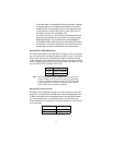
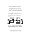
Connecting to a “DTE” Device
The serial port on the 2701/B (RS-530 version) and 2701/C (V.35 ver-
sion) is hard-wired as a DCE. Therefore these modules “want” to plug
into a DTE such as a terminal, PC or host. When making the connection
to your DTE device, use a straight through cable of the shortest possible
length—we recommend 6 feet or less. When purchasing or constructing
an interface cable, please refer to the pin diagrams in Appendix D as a
guide.