


2
CONTENTS
1.0 Warranty Information ................................................................. 4
1.1 Radio and TV Interference............................................................ 4
1.2 CE Notice...................................................................................... 4
1.3 Service.......................................................................................... 5
2.0 General Information.................................................................... 6
2.1 Features........................................................................................ 6
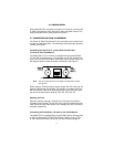
2.2 Description.................................................................................... 6
3.0 Configuration .............................................................................. 7
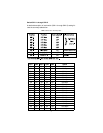
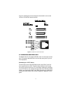
3.1 DIP Switch Configuration.............................................................. 7
Switch SW1-1 through SW1-5...................................................... 8
SW1-6 and SW1-7 Clock Modes.................................................. 9
SW1-8: Enable/Disable Loop Tests from DTE ........................... 10
Switch SW2-1 Line Coding: HDB3 (default)............................... 10
Switch SW2-2: CRC-4 Multiframe .............................................. 11
Switch SW2-3 Data Inversion..................................................... 11
Switch SW2-4: Remote Digital Loopback Type.......................... 12
Switch SW2-5 Front Panel Switches.......................................... 12
Switch SW2-6: V.54 Response Disabled (default) ..................... 12
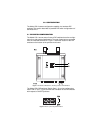
4.0 Installation................................................................................. 13
4.1 Connecting to the G.703 Network............................................... 13
Connecting the 2701/D (X.21 version) Dual Coaxial Cable
(75 ohm) to the G.703 Network .................................................. 13
Opening the Case....................................................................... 13
Connecting the Twisted Pair (120 ohm) to the G.703 Network .. 13
4.2 Connecting the Serial Port.......................................................... 14
Connecting to a “DTE” Device.................................................... 14
Connecting to a “DCE” Device ................................................... 15
Configuring the X.21 Interface (2701/D)..................................... 15
4.3 Power Connection ...................................................................... 15
Universal AC Power (100–240 VAC).......................................... 15
DC Power ................................................................................... 16
5.0 Operation................................................................................... 17
5.1 Power-up .................................................................................... 17
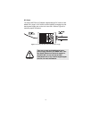
5.2 LED Status Monitors................................................................... 17
5.3 Loop (V.54 & Telco) Diagnostics ................................................ 18
Operating Local Loopback (LL) .................................................. 18
Operating Remote Digital Loopback (RL)................................... 19
CSU Loop................................................................................... 20
Using the V.52 (BER) Test Pattern Generator ........................... 20
A Specifications ........................................................................... 21
A.1 Network Data Rate ...................................................................... 21
A.2 Network Connector ..................................................................... 21
A.3 Nominal Impedance ................................................................... 21
A.4 Line Coding ................................................................................ 21