


15
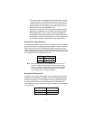
Connecting to a “DCE” Device
If the Model 2701 serial interface is hard-wired as a DCE (all except the
X.21 version), you must use a null modem cable when connecting to a
modem, multiplexer or other DCE device. This cable should be of the
shortest possible length—we recommend 6 feet or less.
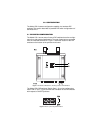
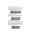
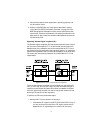
Configuring the X.21 Interface (2701/D)
The serial port on the X.21 interface is default wired as a DCE, but may
be switched to a DTE. This is done by reversing the orientation of the
DCE/DTE strap, as described below:
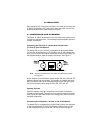
To reverse DCE/DTE orientation, remove the top case. Refer to section
“Opening the Case” on page 13
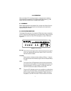
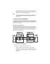
The DCE/DTE strap is located near the DB15 connector on the top side
of the board. The arrows on the top of the strap indicate the configuration
of the X.21 port (for example, if the DCE arrows are pointing toward the
DB-15 connector, the X.21 port is wired as a DCE). Reverse the DCE/
DTE orientation by pulling the strap out of its socket, rotating it 180º, then
plugging the strap back into the socket. You will see that the DCE/DTE
arrows now point in the opposite directions, showing the new configura-
tion of the X.21 port.
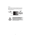
Note
If the 2701/D is configured as a DTE, the clocking mode must be
set for external clock.
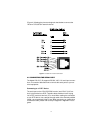
4.3 POWER CONNECTION
Universal AC Power (100–240 VAC)
The Model 2701 uses a 5VDC, 2A universal input 100–240 VAC, power
supply (center pin is +5V). The universal input power supply has a male
IEC-320 power entry connector. This power supply connects to the
Model 2701 by means of a barrel jack on the rear panel. Many interna-
tional power cords are available for the universal power supply.
The Model 2701 powers up as soon as it is plugged into an AC outlet--
there is no power switch.