


19
2. Verify that the data terminal equipment is operating properly and
can be used for a test.
3. Perform a V.52 BER (bit error rate) test as described in section
“Using the V.52 (BER) Test Pattern Generator” on page 20. If the
BER test equipment indicates no faults, but the data terminal indi-
cates a fault, follow the manufacturer’s checkout procedures for the
data terminal. Also, check the interface cable between the terminal
and the Model 2701.
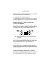
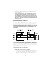
Operating Remote Digital Loopback (RL)
The Remote Digital Loopback (RL) test checks the performance of both
the local and remote NetLink-E1™, as well as the communication link
between them. Any characters sent to the remote NetLink-E1™ in this
test mode will be returned back to the originating device (i.e, characters
typed on the keyboard of the local terminal will appear on the local termi-
nal screen after having been passed to the remote NetLink-E1™ and
looped back).
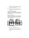
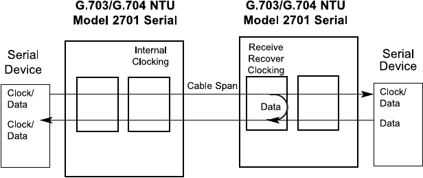
Figure 8.
Remote Loop in a Network Extension Application
There are two Remote Loops that can be initiated from the NetLink-E1
unit: (1) V.54 Loop, and; (2) CSU Loop. The user can select the type of
loop that can be initiated by Switch S2-4. When a loopback is initiated
this is the type of loop that the unit uses to loop up the remote unit and
which type of loop the unit will respond to.
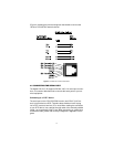
To perform an RDL test, follow these steps:
1. Activate RDL. This may be done in two ways:
— Activate the “RL” signal on the DTE (2701/B and 2701/C only). If
you are not sure which lead is the “RL” signal, please refer to
Appendix B or C, depending on the version you are using.