


Installing the OnSite 2884 26
OnSite Model 2884 User Manual 3 • OnSite installation
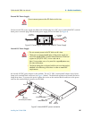
External AC Power Supply.
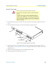
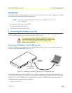
1. Insert the barrel type connector end of the AC power cord into the external power supply connector (see
figure 7).
2. Insert the female end of the power cord into the internal power supply connector.
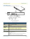
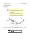
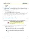
Figure 7. Power connector location on rear panel
3. Verify that the AC power cord included with your router is compatible with local standards. If it is not,
refer to chapter 5, “Contacting Patton for assistance” on page 32 to find out how to replace it with a com-
patible power cord.
4. Connect the male end of the power cord to an appropriate power outlet.
5. Verify that the green Power LED is lit (see figure 6).
•
Do not connect power to the AC Mains at this time.
•
The external power adapter shall be a listed Limited Power
Source.
•
The 2884 external power supply automatically adjusts to
accept an input voltage from 100 to 240 VAC (50/60 Hz).
Verify that the proper voltage is present before plugging the
power cord into the receptacle. Failure to do so could result in
equipment damage.
CAUTIONWARNING
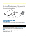
RS-232
Console
Reset
3
2
1
0
T1/E1
Power
T1/E1
Ports 0-3
Console
RS-232 port
ETH 0
10/100/1000Base-T port
ETH 1
10/100/1000Base-T port
RESET
button
12V, 1.25A
– +
1
0
ETH