


Installing the OnSite 2884 27
OnSite Model 2884 User Manual 3 • OnSite installation
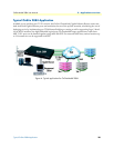
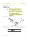
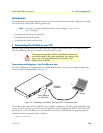
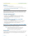
External DC Power Supply.
On the external DC power supply, the black and red leads plug into a DC source (nominal 48VDC) and the
barrel power connector plugs into the barrel power supply jack on the 2884. (See figure 8).
Figure 8. Connecting DC Power to the 2884 DC Power Supply
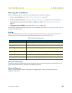
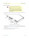
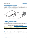
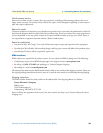
Internal DC Power Supply.
An internal 48 VDC power adapter is also available. The 36-72 VDC (nominal 48V) adapter uses a ferrite
clamp and a terminal block connector (see Figure 9 below). The black and red leads wrap around the ferrite
clamp three times. To connect the power, tighten the screws on the terminal block connector on the power
cord into the terminal block connector on the 2884.
Figure 9. Internal 48VDC power connection
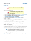
Do not connect power to the DC Mains at this time.
•
Do not connect power to the DC Mains at this time.
•
There are no user-serviceable parts in the power supply sec
tion of the Model 2884. Contact Patton Electronics Technical
support at (301)975-1007, via our web site at
http://www.patton.com, or by e-mail at support@patton.com,
for more information.
•
The ferrite clamp that is shipped with the unit must be used as
detailed in the following instructions in order to meet EMC
requirements.
WARNING
To Power
Supply Jack
To -48VDC
Source
-Vin
+Vin
SWITCHING POWER SUPPLY
MODEL : SYD1106-0505
INPUT : 36-60V 0.2A MAX
OUTPUT : +5V 1.0A
OUTPUT POWER : 5W MAX
S/N: G01234567890
MADE IN CHINA BY SUNNY
Black lead (-V
)
Red lead (+V)
Barrel power connector
WARNING
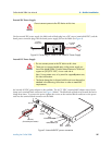
RS-232
Console
Reset
3
2
1
0
T1/E1
Power
T1/E1
Ports 0-3
Console
RS-232 port
ETH 0
10/100/1000Base-T port
ETH 1
10/100/1000Base-T port
RESET
button
1
0
ETH
36-72V, 1.0A
Power
+ E –
Ferrite clamp
(for internal DC power connection)