


Introduction 42
Model 3088A Series Getting Started Guide 4 • Operation
Introduction
Once the Model 3088A is properly configured and installed, it should operate transparently. The following
sections describe power-up, reading the LED status monitors, and using the built-in loopback test modes.
Power-up
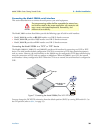
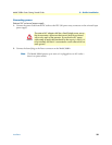
To apply power to the Model 3088A, first be sure that you have read section “Power input connector” on
page 16, and that the unit is connected to the appropriate power source. Power up the unit.
LED status monitors
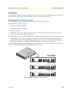
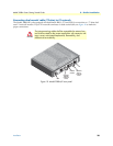
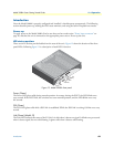
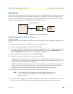
There are six LEDs that provide feedback on the state of the unit. Figure 12 shows the location of the front
panel LEDs. Following figure 12 is a description of each LED’s function.
Figure 12. Model 3088A front panel
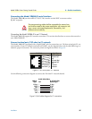
Power (Green)
The Power LED glows solid during normal operation. At startup, during the POST, the LED blinks once
every second. If the POST fails, the unit does not enter normal operation, and the LED blinks once every
0.4 seconds.
DSL (Green)
The DSL LED glows solid while a DSL link is established. While the DSL link is training it blinks once every
second.
Link (Green) (Model /K)
The Link LED indicates the status of the E1 link. It is dark when it detects no signal. It blinks once per second
when it detects signal, but not valid framing. It glows solid when it detects valid framing.
DSL
Terminal
TM / ERR
Power
Activity
Link