Introduction 43
Model 3088A Series Getting Started Guide 4 • Operation
Terminal (Green)
The Terminal LED glows solid under the following circumstances:
• 3088A/CA with V.35 interface and 3088A/A with RS-232 interface: if the serial interface has asserted
DTR
• 3088A/D with the X.21 interface
- Configured as DCE: Indicates that the “Control” signals have been asserted.
- Configured as DTE: Indicates that the “Indication” signals have been asserted
TM/ER (Yellow)
The TM/ER LED is used to indicate that a test mode is in progress or an error has been detected. It blinks
once every second while a test mode is starting. It glows solid while a test mode is in progress. It blinks once if
an error is detected either during a test mode, or in normal DSL operation.
LOS (Red) [Model /K]
The LOS LED blinks once per second to indicate either framing errors or clock slips. Clock slips are often
caused by a mis-configured clock mode.
Link (Green)
The Link LED shows that there is an active physical connection to the Console.
Activity (Green)
The Activity LED shows that there is data being transferred through the Console connection. During a soft-
ware upgrade procedure, if the Activity LED is on for an unusually long time, there is a problem with the
upgrade, and the device should be restarted. The TFTP server should be checked (normal upgrades take about
10 seconds on a 100mbit link).
Test modes
The 3088A offers test modes in the form of loopbacks, PRBS pattern generators, and combinations of both.
This section discusses how the test modes work.
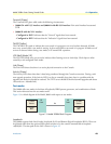
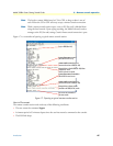
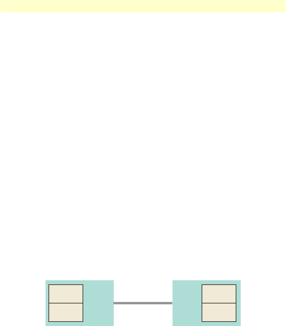
Figure 13 is a block diagram of the Model 3088A with respect to test modes.
Figure 13. Model 3088A Block Diagram
Loopbacks
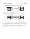
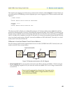
The 3088A supports both Local Analog Loopbacks (LAL) and Remote Digital Loopbacks (RDL). These can
be initiated either from the optional front panel switches or by the console command dsl set loopback
<off|lal|rdl>. The data path for the LAL is shown in figure 14.
DSL
Framer
511 Pattern
Generator
511 BER
Meter
DSL
Framer
511 Pattern
Generator
511 BER
Meter
Line


