


2.0 GENERAL INFORMATION
Thank you for your purchase of this Patton Electronics product.
This product has been thoroughly inspected and tested and is
warranted for One Year parts and labor. If any questions or problems
arise during installation or use of this product, please do not hesitate to
contact Patton Electronics Customer Service at (301) 975-1007.
2.1 FEATURES
• Data rates of 32, 56 and 64 kbps
• Distances to 6 miles (9.7km)
• Switch-selectable carrier control
• Synchronous X.21 operation
• Frequency Shift Keying (FSK) modulation
• DCE/DTE Switchable
• Point-to-point operation over 2 unconditioned twisted pair
• V.54 loopback tests and V.52 compliant BER tests
• 6 LED indicators
• Externally powered
• Transformer isolation
• Silicon Avalanche Diode surge protection
• Made in the U.S.A.
2.2 DESCRIPTION
The Model 1075 KiloModem II X.21 Short Range Modem
supports synchronous data rates of 32, 56 and 64 Kbps. Synchronous
transmit clock options are internal, external and receive recover clock.
Deriving power from a 9V DC wall-mount transformer, the Model 1075
supports extended distances to 6 miles (9.7km) over 2 unconditioned
twisted pairs.
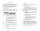
The Model 1075 incorporates two V.54 test modes (local analog
loop and remote digital loop) that are activated by a tiny front panel
switch. In addition, a built-in V.52 Bit Error Test (BER) test generator
that outputs 511 and 511E bit patterns can also be controlled by a
switch on the case. Six LED indicators monitor transmit data, receive
data, control, indication, test mode (TM) and Error Status (ER). For
protection against ground loops and transient surges, the Model 1075
incorporates both isolation transformers and Silicon Avalanche Diode
surge suppressors.
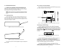
Housed in a miniature ABS plastic case, the Model 1075 comes
equipped with a female DB-15 connector and a choice of twisted pair
interfaces (RJ-11 jack or RJ-45 jack).
3.0 CONFIGURATION
The Model 1075 is easy to install and is ruggedly designed for
excellent reliability. The following instructions will help you to properly
configure the Model 1075.
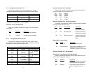
3.1 CONFIGURATION SWITCHES
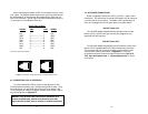
The Model 1075 uses a unique set of 16 external mini DIP
switches that allow configuration to wide range of applications. The 16
external switches are grouped into two eight-switch sets, and are
externally accessible from the underside of the Model 1075 (See Figure
1).
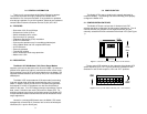
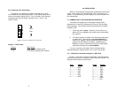
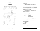
The two sets of DIP switches on the underside of the Model 1075
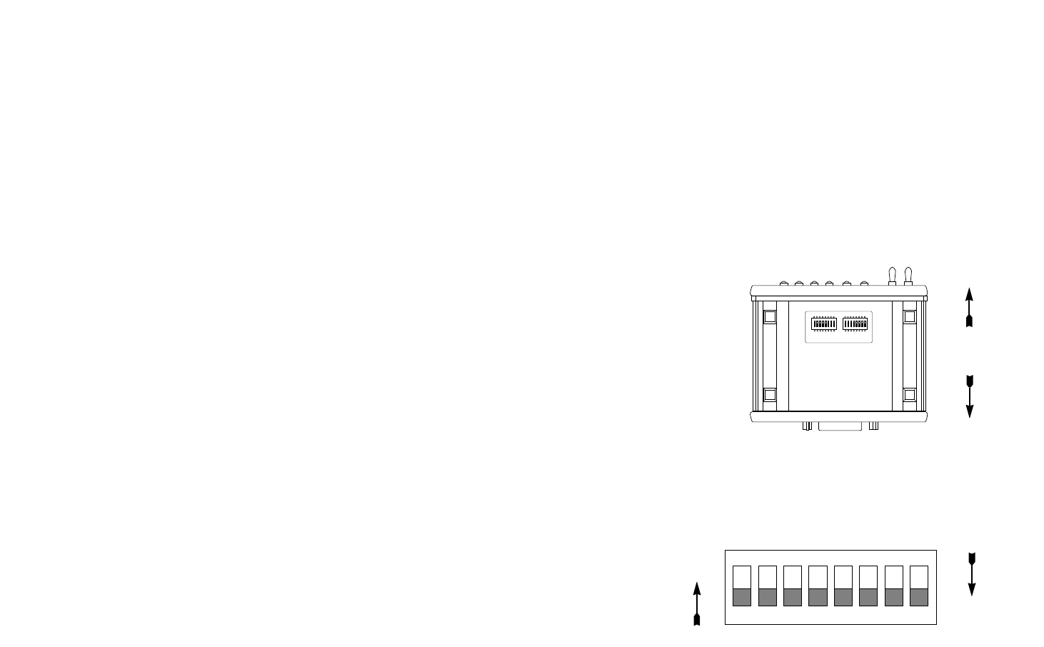
will be referred to as S1, S2. Figure 2 shows the orientation of DIP
Switches S1 and S2 with respect to “ON” and “OFF” positions.
4
3
12345678
ON
Figure 2. Close-up of DIP Switches Showing “ON” / “OFF” Positions
ON
OFF
ON
12345678
ON
12345678
S1 S2
Figure 1. Underside of the 1075 Showing Location of DIP Switches
Front
Rear