


C. If the BER test equipment indicates a fault, and the Local
Analog Loopback test was successful for both Model 1075s,
you may have a problem with the twisted pair line between the
modems. You should then check the twisted pair line for
proper connections and continuity.
5.2.3 How to Use the V.52 BER Test Independently
The V.52 BER test can be used independently of the V.54 loopback
tests. This requires two operators: one to initiate and monitor the test
at the local Model 1075, and one at the remote Model 1075. To use the
V.52 BER test by itself, both operators should simultaneously follow
these steps:
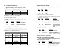
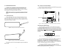
1. Locate the 511/511E toggle switch on the front panel of the
1075 and move it UP. This activates the V.52 BER test mode
and transmits a 511 test pattern to the other unit. If any errors
are present, the receiving modem’s red Error LED will blink
sporadically. For this test to work, make sure the 511 switch
on both Model 1075s is on.
2. If the test indicates no errors are present, move the V.52
toggle switch DOWN, activating the 511/E test with errors
present. If the test is working properly, the receiving modem's
red Error LED will blink regularly. A successful 511/E test will
confirm that the link is in place, and that the Model 1075’s
built in 511 generator and detector are working properly.
5.3 POWER-DOWN
There is no power switch on the Model 1075. You turn it off by
unplugging the AC power adapter from the wall.
APPENDIX A
PATTON MODEL 1075 SPECIFICATIONS
Approvals: CE European Directives
DTE/DCE I/F: X.21 DB15F DCE or DTE, EIA RS-422
Compliant
Compatibility: 1035, 1045 , 1075, 1080A, 1090 series units
Transmission
Format: Synchronous
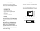
Transmission Unconditioned twisted pair 19 - 26 AWG
Line Interface: Externally accessible RJ-45 (RJ-11
Optional)
Clock Internal, External and Network (Receive
Recover)
Distance: Up to 6 miles (9.7km)
Interfaces: CCITT/ITU X.21
Data Rates: 32, 56 and 64 Kbps (switch selectable)
Isolation: 1500V RMS via isolation transformers
Surge Protection: IEC-801-S, Level 2, 1kV
Carrier Control Constantly on or Controlled by “Control”
from DTE device (DCE mode) or
“Indication” from DCE device (DTE mode)
Connectors: DB-15 female
RJ-11 or RJ-45 on line side
Power Supply: 9V DC wall-mount transformer, 200mA
Temperature
Range: 0-60°C (32-140°F)
Altitude: 0-15,000 feet
Humidity: 5 to 95% noncondensing
Dimensions: 1.54H x4.1”W x 3.7”D
Power Options: 120 VAC 50/60Hz, external transformer;
230 VAC 50/60Hz, external transformer
Weight: 2.5 lbs. (1.1 Kg)
15 16