


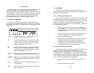


4.3 AC POWER CONNECTIONS
Power is supplied to the Model 1075 by a 9 VDC, 1 A wall mount
transformer. This transformer connects to the Model 1075 by means of
a cannon jack on the rear panel. The Model 1075 is powered-up as
soon as it is plugged into an AC outlet–there is no power switch.
120 VAC Power (US)
The 120 VAC adapter supplied with the standard version of the
Model 1075 is a “wall mount” type, and may be plugged into any
approved 120 VAC wall plug.
230 VAC Power (IEC)
The 230 VAC adapter supplied with the international version of the
Model 1075 is equipped with an IEC-320 shrouded male connector.
This connects with one of several available country-specific power
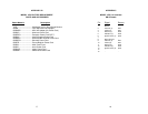
cords (see the ordering information in Appendix C.) You may
purchase these power cords from Patton Electronics at: (301) 975-
1007; http://www.patton.com; or, support@patton.com; or from a
local vendor.
12
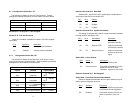
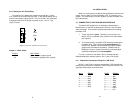
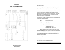
When connecting two Model 1075s, it is necessary to use a "cross-
over" cable. The diagram below shows how a cross-over cable should
be constructed for an environment where both Model 1075s use a 8-
wire RJ-45 connector. Similar logic should be followed when using RJ-
11 connectors or a combination of the two.
RJ-45 Cable (8-W
ire)
SIGNAL PIN# PIN# SIGNAL
N/C 1 1 N/C
GND
†
2-----------------------7 GND
†
RCV 3-----------------------5 XMT
XMT 4-----------------------6 RCV
XMT 5-----------------------3 RCV
RCV 6-----------------------4 XMT
GND
†
7-----------------------2 GND
†
N/C 8 8 N/C
†
Connection to ground is optional
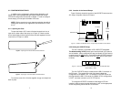
4.2 CONNECTION TO X.21 INTERFACE
To connect the Model 1075 to a piece of data terminal or data
communications hardware, use a
straight through
DB-15 cable. Plug
the cable directly into the DB-25 port on the rear of the Model 1060.
If it is necessary to construct a special interface cable, please refer to
the pinout diagrams in Appendix C.
Notice! Any terminal cable connected to the Model 1075
must be shielded cable, and the outer shield must be 360
degree bonded–at both ends–to a metal or metalized backshell.
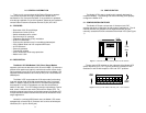
1
2
3
4
5
6
1
2
3
4
5
6
7
8
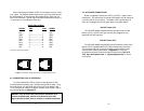
11
Figure 8. Pin Number Assignments for RJ11 and RJ45 Modular Jacks