


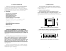
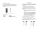
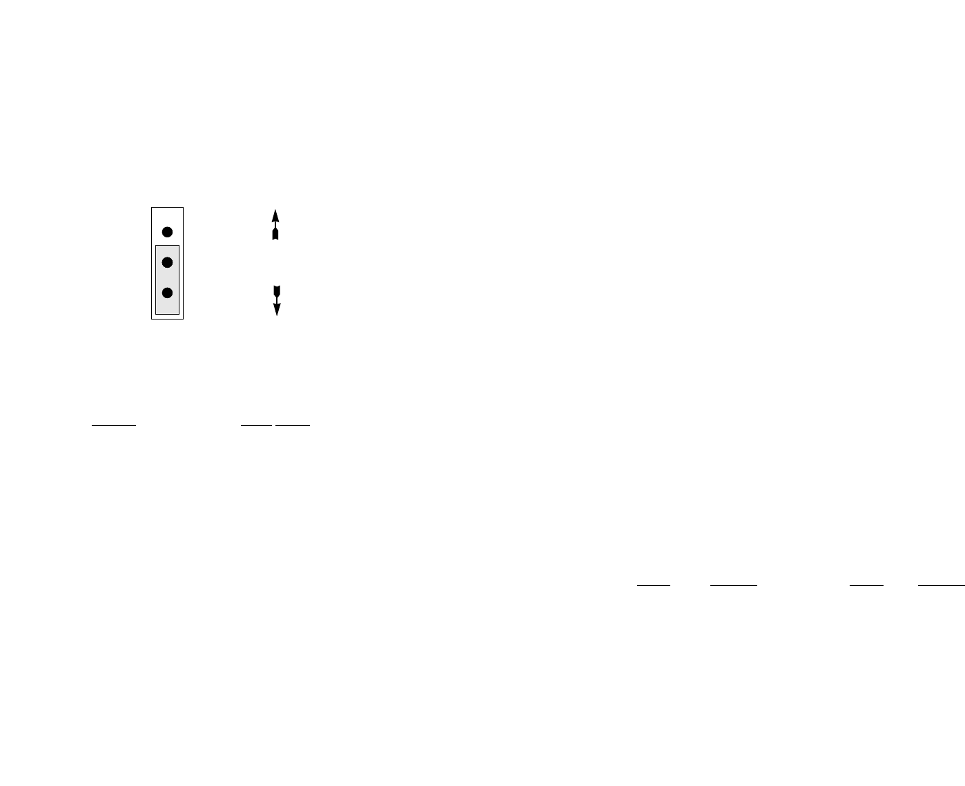
3.2.4 Setting the JP1 Shield Strap
The setting of JP1 determines whether the shield (pin 1) of the
X.21 interface is connected signal ground. In the default setting, DB-15
shield is connected to signal ground. The X.21 shield is not connected
to signal ground when the jumper is placed on pins 1 and 2 . See
Figure 7, below.
Jumper 1: DB15 Shield
Position
DB15 Shield
1-2
Not connected to signal ground
2-3 Connected to signal ground
(default)
9
4.0 INSTALLATION
When you have properly configured the configuration switches and
straps, you are ready to connect the Model 1075 to connect to your
system. This section tells you how to properly connect the Model 1075
to the twisted pair.
4.1 CONNECTION TO THE TWISTED PAIR INTERFACE
The Model 1075 supports full or half duplex communication
between two X.21 devices at distances to 6 miles (9.7 km) and data
rates to 64 kbps. There are two essential requirements for installing
the Model 1075:
1. These units work in pairs. Therefore, you must have one
Model 1075 (or compatible unit) at each end of a two twisted
pair interface.
2. To function properly, the Model 1075 needs two twisted pairs
of metallic wire. These pairs must be unconditioned, dry
metallic wire, between 19 and 26 AWG (the higher number
gauges may limit distance somewhat). Standard dial-up
telephone circuits, or leased circuits that run through signal
equalization equipment, are not acceptable.
For your convenience, the Model 1075 is available with two
different twisted pair interface options: RJ-11 jack or RJ-45 jack.
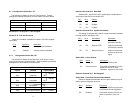
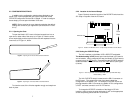
4.1.1 Twisted Pair Connection Using RJ-11 OR RJ-45
The RJ-11 and RJ-45 connectors on the Model 1075's twisted pair
interface are pre-wired for a standard TELCO wiring environment. The
signal/pin relationships are shown below.
RJ-1
1 SIGNAL RJ-45 SIGNAL
1...................GND 1 .................N/C
2...................RCV 2 .................GND
3...................XMT 3 .................RCV
4...................XMT 4 .................XMT
5...................RCV 5 .................XMT
6...................GND 6 .................RCV
7 .................GND
8 .................N/C
10
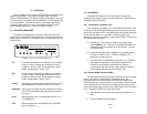
Figure 7. Jumper JP1 Orientation on the PC board
1
2
3
Front
Rear