


27
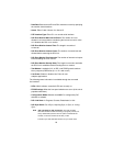
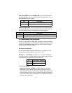
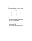
DTE Shield (DB-15 Pin 1) & FRGND (JB3). In the connected position,
this strap links DB-15 pin 1 & frame ground. In the open position, pin 1 is
disconnected from frame ground.
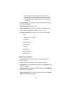
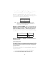
SGND & FRGND (JB4). In the connected position, this strap links DB-15
pin 8 (Signal Ground) and frame ground through a 100 ohm resistor. In
the open position, pin 8 is connected directly to frame ground.
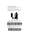
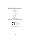
3.8 CONFIGURING THE E1 REAR CARD
The E1 rear card features conÞguration capability via hardware switches
and jumpers. Sections 4.1 and 4.2 describe all switch and jumper conÞg-
urations for the 3088RC/K model. Section 4.3 describes the conÞgura-
tion required for your mDSL modem.
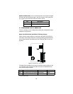
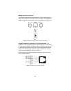
DIP Switch ConÞguration
The E1 card has eight internal DIP switches (S1-1 through S1-8). The
DIP switches can be conÞgured as either “On” or “Off.”
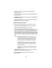
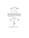
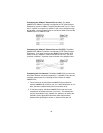
Switch S1-1 : Line Coding. Use Switch S1-1 to control the Network
Line Coding options. Set these options to be the same as the Line Cod-
ing that has been provided by your Service Provider.
Line Coding Options:
• High Density Bipolar 3 (HDB3): In HDB3 coding, the transmitter
deliberately inserts a bipolar violation when excessive zeros in the
data stream are detected. The receiver recognizes these special viola-
tions and decodes them as zeros. This method enables the network to
meet minimum pulse density requirements. Use HDB3 unless AMI is
required in your application .
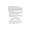
JB3 Description
Position 1&2 DTE Shield (Pin 1) and FRGND Connected
Position 2&3 DTE Shield (Pin 1) and FRGND Not Connected
JB4 Description
Position 1&2 SGND (Pin 8) and FRGND Connected through a 100-ohm resistor
Position 2&3 SGND (Pin 8) and FRGND Directly Connected
S1-1 Line Framing & Coding
Off HDB3
On AMI