28
• Alternate Mark Inversion (AMI): AMI coding does not inherently
account for ones density. To meet this requirement, you should ensure
that the data inherently meets pulse density requirements.
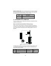
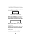
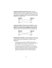
Switch S1-2 : CRC-4 Multiframe. CRC-4 Multiframe uses Time Slot
zero to carry CRC-4 information. When CRC-4 is enabled (ON), the unit
synchronizes to the CRC-4 multi-frame protocol.
Note When the data rate is set to 2048 Kbps, K Module transmits
user data on all 32 timeslots, ignoring framing information. In
this case, Switch S1-2 will be ignored.
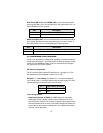
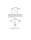
Switch S1-3 : Clear Channel Mode. When S1-3 is at Off position, the
K Module is running in G.703 clear channel mode. When S1-3 is at On
position, the K Module is running in G.704 framed mode. When the K
Module is set to framed mode, channel 0 will be used to pass G.704
framing information which results in a maximum bandwidth of 1984kbps
for user data.
Switch S1-4 Through S1-8 : Reserved. Reserved for future use and
should be set to OFF.
Jumper ConÞguration
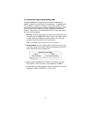
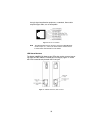
The 3088RC/K model has four jumpers (two position headers): JP4, JP5,
JP6, and JP7. These jumpers are used to select input and output imped-
ance matching between the module and external line. See Appendix E
for jumper locations.
The following is a description of the jumper settings with respect to the
front panel connectors.
1. For a 75 ohm connection (coax) install JP4 - JP7 (default).
2. For a 120 ohm connection (RJ-48C) remove JP4 - JP7.
S1-2 Option
Off On
Disabled Enabled
S1-3 Option
Off On
Clear Channel Mode (G.703) Framed Mode
(G.704)


