


Installing the SN-DTA 25
SN-DTA User Manual 3 • SN-DTA installation
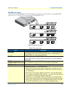
The Ethernet port (ETH) includes an automatic MDX (auto-crossover) feature that automatically detects the
cable configuration and adjusts accordingly. The feature allow you to use a straight-through Ethernet cable to
connect to an Ethernet hub or switch. Typically the hub or switch will connect to a router that provides the the
local-residential IP network with broadband Internet access.
Using the included black Ethernet cable, connect the RJ-45 Ethernet WAN port on your SN-DTA (labeled
ETH), to an Ethernet hub or switch on the same network as your PC.
For details on the Ethernet port pinout and cables, refer to Appendix C, “Cabling” on page 43 and Appendix
D, “Port pin-outs” on page 46.
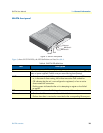
Connecting the SN-DTA to the power supply
1. Insert the barrel-type connector end of the AC power supply into the 12V DC, 1.0A port (see figure 2 on
page 17).
2. Verify that the AC power cord included with your SN-DTA is compatible with local standards. If it is not,
refer to chapter 5, “Contacting Patton for assistance” on page 33 to find out how to replace it with a com-
patible power cord.
3. Connect the male end of the AC power supply power cord to an appropriate AC power outlet.
4. Verify that the green Power LED is lit (see figure 3 on page 18).
External S-Bus power supply
Do not use an external power supply for ISDN terminals connected to the SN-DTA. The SN-DTA supplies S-
Bus line power to ISDN terminals connected to the BRI port, so external power supplies are not required for
the ISDN terminals.
Congratulations, you have finished installing the SN-DTA ! Now go to chapter 4, “SN-DTA initial configura-
tion” on page 26.
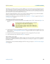
The external power supply automatically adjusts to accept an
input voltage from 100 to 240 VAC (50/60 Hz).
Verify that the proper voltage is present before plugging the
power cord into the receptacle. Failure to do so could result in
equipment damage.