


14
Note
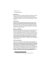
The connection diagram in Figure 1 on page 7 includes an
optional RJ-11 modular T adapter so the USB modem and a
telephone can share the same telephone wall jack. If you will not
be sharing the wall jack, it is not necessary to install a T adapter.
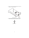
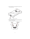
1. Connect one end of the USB cable supplied with the modem to the
USB port on the modem (see Figure 4 on page 9).
2. Connect the other end of the cable to one of the PC’s USB ports.
The port is usually labeled with the symbol shown in Figure 5 on
page 9.
3. Plug one end of the RJ-11 cable supplied with the modem into the
RJ-11 jack (see Figure 6 on page 10).
4. Plug the other end of the RJ-11 cable into the modular jack on the
wall outlet or optional T adapter.
5. Verify that the red POWER LED on the modem (see Figure 7 on
page 10) is lit.
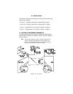
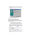
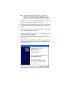
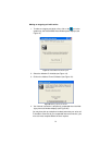
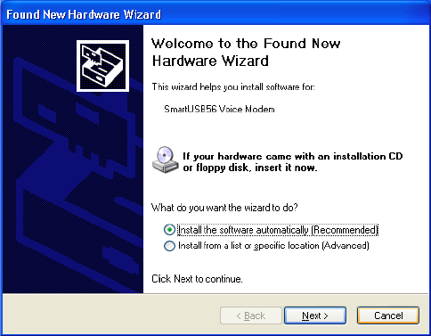
6. Windows XP detects the USB modem automatically and displays
the message
Found New Hardware Wizard”,
click
Cancel
to con-
tinue (see Figure 10).
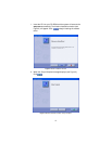
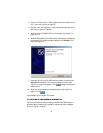
Figure 11.
Found New Hardware Wizard