


ISSUED: 08-15-07 SHEET #: 055-9491-6 06-21-10
Visit the Peerless Web Site at www.peerlessmounts.com
10 of 13
For customer care call 1-800-865-2112 or 708-865-8870.
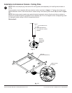
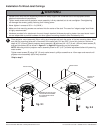
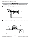
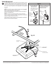
Cable Management
To make an opening to route cables through projector mount
assembly, adjust projector mount assembly to full upward tilt
position by turning knob for tilt adjustment as shown in fi gure
8.2. Left or right roll position can be adjusted if more space is
required.
NOTE: Be certain tamper resistant screws are not engaged
before making adjustments (see step 9).
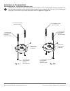
Route cables through top of extension column as shown in
fi gure 8.1 and fi gure 8.2.
NOTE: A method for assisting cables through extension
column may be required (example: string tied to connector to
help pull through extension column).
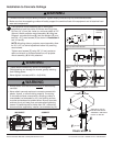
Route cables through projector mount assembly as shown in
fi gure 8.2 and connect to projector.
8
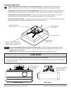
DO NOT
CRIMP
WIRES
BEND WIRES OF RCA
PLUGS IN OPPOSITE
DIRECTION
NOTE: INNER DIAMETER OF
EXTENSION COLUMN MAY NOT
ALLOW PASSAGE FOR ALL
CONNECTOR TYPES.
ROUTE
CONNECTOR
THROUGH
FIRST
CABLES WITH COMBINATION
OF VGA CONNECTOR
AND RCA PLUGS
INNER
DIAMETER OF
EXTENSION
COLUMN
CABLE
CONNECTOR
fi g. 8.2
fi g. 8.1
EXTENSION
COLUMN
OPENING FOR
ROUTING CABLES
KNOB FOR TILT
ADJUSTMENT
KNOB FOR ROLL
ADJUSTMENT