


ISSUED: 08-15-07 SHEET #: 055-9491-6 06-21-10
Visit the Peerless Web Site at www.peerlessmounts.com
5 of 13
For customer care call 1-800-865-2112 or 708-865-8870.
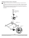
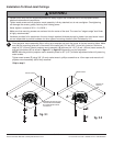
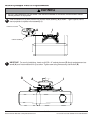
Place projector mount assembly (A) on ceiling as a template and mark the center of the two mounting holes. Make
sure that the mounting holes are in the center of the wood joist. Drill two 5/32" (4 mm) dia. holes to a minimum
depth of 2.5" (64 mm). Attach projector mount assembly (A) with two #14 x 2.5" (6 mm x 65 mm) wood screws (F)
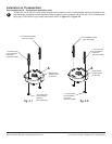
and two fl at washers (E) as shown in fi gure 2.1 or fi gure 2.2 depending on joist orientation.
NOTE: Mounting slots on projector mount assembly allow for 30° (±15°) of swivel adjustment before fully securing
wood screws.
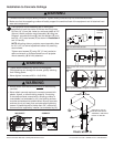
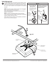
Tighten wood screws (F) using 3/8" (10 mm) socket wrench, phillips screwdriver or 10mm open end wrench until
projector mount assembly (A) is fi rmly attached.
Installation To Wood Joist Ceilings
FRONT OF
MOUNT
2
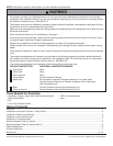
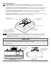
• Installer must verify that the supporting surface will safely support the combined load of the equipment and all
attached hardware and components.
• Tighten wood screws so that projector mount assembly is fi rmly attached, but do not overtighten. Overtightening
can damage the screws, greatly reducing their holding power.
• Never tighten in excess of 80 in. • lb (9 N.M.).
• Make sure that mounting screws are anchored into the center of the stud. The use of an "edge to edge" stud fi nder
is highly recommended.
• Hardware provided is for attachment of mount through standard thickness drywall or plaster into wood studs. Install-
ers are responsible to provide hardware for other types of mounting situations (Not Evaluated by UL).
WARNING
Skip to step 5.
ARROW ON TOP OF PRO-
JECTOR MOUNT ASSEM-
BLY INDICATES FRONT
OF MOUNT
F
F
A
WOOD JOIST
E
E
WOOD JOIST
A
fi g. 2.1
fi g. 2.2