


14 C2607M (2/07)
Installation
PACKAGE CONTENTS
The following items are supplied:
1 FX82052 module
1 Regulated switching power supply with four plug adapters (North American, Australian, U.K.,
and European configurations); 100-240 VAC, 50-60 Hz input, 12 VDC output
1 Wall clip with two 4-40 x 0.250-inch Phillips pan head screws with lock washers (for attachment
of single module to wall)
1 FX82052 Unmanaged Ethernet Switch Installation manual
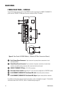
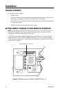
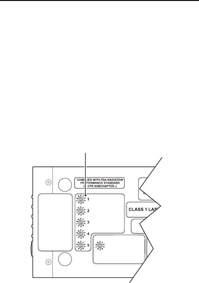
SETTING 10BASE-T/100BASE-TX PORT MODES OF OPERATION
NOTE: As a matter of convenience, it is recommended that you verify the modes of operation for
each 10BASE-T/100BASE-TX port and then change the mode settings—if necessary—before
mounting the FX82052 module into a rack or onto a wall.
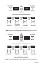
The FX82052 module provides various configuration options that allow you to select the desired
modes of operation for each 10BASE-T/100BASE-TX port (ports 1-5). You can select the desired
modes of operation by means of a TX Mode switch that is provided on the bottom of the module for
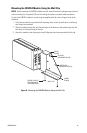
each port (refer to Figure 6).
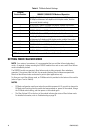
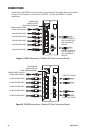
Figure 6. TX Mode Switches for 10BASE-T/100BASE-TX Ports 1-5
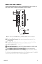
FX Mode
0. Independent A & B
1. Auto Failover
2. Auto Failover
3-9 NOT USED
A is Primary
B is Primary
TX Mode
0. Auto Neg / Dis FC
1. 100 FD / Dis FC
2. 100 HD / Dis FC
3. 10 FD / Dis FC
4. 10 HD / Dis FC
5. Auto Neg / En FC
6. 100 FD / En FC
7. 100 HD / En FC
8. 10 FD / En FC
9. 10 HD / En FC
TX MODE SWITCHES - PORTS 1-5