


C2607M (2/07) 21
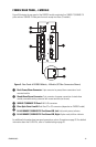
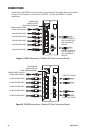
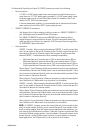
As illustrated in Figure 9 and in Figure 10, FX82052 connections consist of the following:
• Power connection
– A 12 VDC or 24 VAC power supply can be used to power the module when used as a
stand-alone unit. A 12 VDC power supply is provided. If a 24 VAC power supply is used,
the power supply must be a Listed Direct Plug-In Power Unit marked as Class 2 and
rated as 24 VAC, 0.50 A (minimum output).
– In extreme temperature conditions, it is recommended that an industrial-rated outdoor
power supply such as the Pelco WCS1-4 power supply be used.
• 10BASE-T/100BASE-TX connections
– Use Category 5e or a higher category of cable to connect to a 10BASE-T/100BASE-TX
port. Cable length must not exceed 328 feet (100 meters).
– The 10BASE-T/100BASE-TX ports are auto MDI/MDI-X ports; therefore, either a
straight-through or crossover cable can be used. The ports automatically detect the
cable type that is used. Refer to the Appendix. RJ-45 Connector Pinouts on page 38 for
RJ-45 MDI/MDI-X pinout information.
• Fiber connections
– FX82052, -2 models: When connecting fiber between FX82052, -2 models, connect fiber
port A of one module to fiber port B of another module. Similarly, connect fiber port B of
one module to fiber port A of another module. Note that ports A and B connect fiber
between FX82052, -2 models because of fiber wavelength compatibility:
• Multimode fiber port A transmits data at 1310 nm and receives data at 850 nm.
Multimode fiber port B transmits data at 850 nm and receives data at 1310 nm.
• Single-mode fiber port A transmits data at 1310 nm and receives data at 1550 nm.
Single-mode fiber port B transmits data at 1550 nm and receives data at 1310 nm.
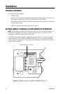
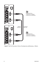
Refer to Figure 11 for an illustration of fiber port connections in point-to-point applications
with redundancy. Note that the FX Mode switch is set on one module to position 1 (fiber
port A connects to the primary fiber link) and is set on the other module to position 2 (fiber
port B connects to the primary fiber link).
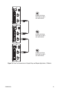
Refer to Figure 12 for an illustration of fiber port connections in drop-and-repeat applica-
tions. Note that the FX Mode switch is set to position 0 on all modules.
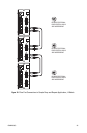
– FX82052, -4 models: When connecting fiber between FX82052, -4 models, connect fiber
port A of one module to fiber port B of another module. Similarly, connect fiber port B of
one module to fiber port A of another module.
Refer to Figure 13 for an illustration of fiber port connections in point-to-point applications
with redundancy. Note that the FX Mode switch is set on one module to position 1 (fiber
port A connects to the primary fiber link) and is set on the other module to position 2 (fiber
port B connects to the primary fiber link).
Refer to Figure 14 for an illustration of fiber port connections in drop-and-repeat applica-
tions. Note that the FX Mode switch is set to position 0 on all modules.
NOTE: On FX82052, -4 models, you can also connect fiber port A of one module to fiber
port A of another module. Similarly, you can connect fiber port B of one module to fiber
port B of another module. Note that in point-to-point applications with redundancy, you
must then set the FX Mode switch as follows. If fiber port A connects to the primary fiber
link, set the FX Mode switch to position 1 on both modules. If fiber port B connects to the
primary fiber link, set the FX Mode switch to position 2 on both modules. In drop-and-
repeat applications, the FX Mode switch is set to position 0 on all modules.