C2462M-B (10/05) 7
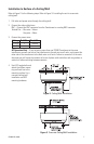
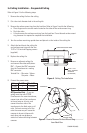
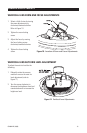
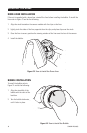
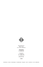
Figure 2. Ceiling/Wall Installation
Installation to Surface of a Ceiling/Wall
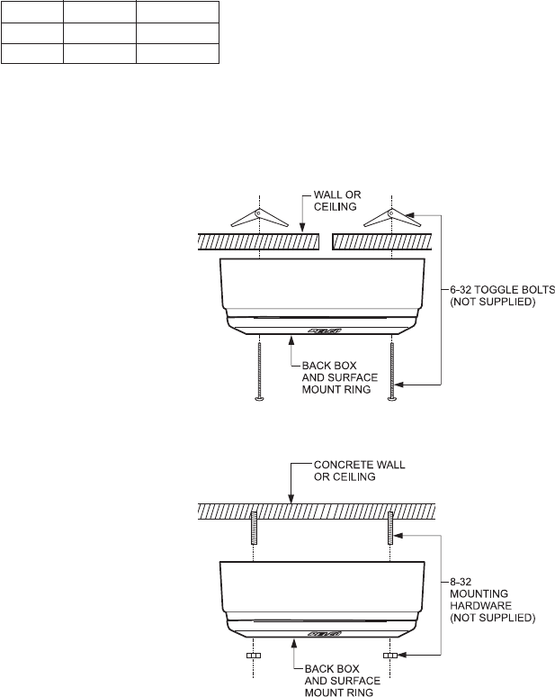
Refer to Figure 2 for the following steps. Refer to Figure 3 if installing the unit to a concrete
ceiling/wall.
1. Pull video and power wires through the ceiling/wall.
2. Connect the video cable/wires.
BNC – Connect the BNC connector from the Camclosure to a mating BNC connector.
Twisted Pair – Blue wire = Video +
Gray wire = Video -
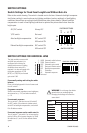
3. Connect the power wires.
AC Operation Only – If you are wiring more than one ICS090 Camclosure to the same
transformer, connect one side of the transformer to the red wire on all units, and connect the
other side of the transformer to the black wire on all units. Failure to connect all of the units
the same way will cause the cameras to be out of phase with each other and may produce a
vertical roll when switching between cameras.
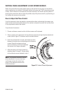
4. Use 6-32 toggle bolts and
attach the surface mount
ring and back box to the
mounting surface. For a
concrete ceiling/wall
installation use 8-32
mounting hardware.
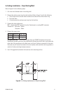
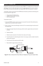
Figure 3. Concrete Ceiling/Wall Installation
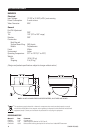
Voltage Red Wire Black Wire
12 VDC + Ground
24 VAC
~~