12 C808M-G (4/05)
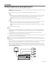
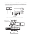
LOOPING CAMERA INPUTS AND TWO MONITOR OUTPUTS
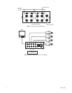
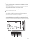
1. Convert the VS5004 to dual-monitor operation. Refer to Figure 8 and do the following:
a. Remove the cover.
b. Remove the rear panel of the chassis.
c. Remove the four screws attaching the PC board to the chassis.
d. Pull the PC board and rear panel assembly out of the chassis.
e. Turn the PC board over and rewire.
2. Convert to looping operation. Refer to Figure 5 and do the following:
NOTE:
Looping and terminated inputs may be mixed.
a. Locate the 75-ohm resistors located on the inside of the rear panel BNC jacks.
b. For each input to be looped, use wire cutters to clip one of the attached resistor leads.
c. Replace the cover.
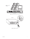
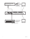
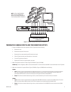
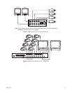
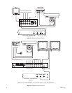
3. Make all equipment connections. Refer to Figure 11 (VS5004) or Figure 12 (VS5008).
(VS5004 only)
In this configuration, MON 1 must be terminated with a 75-ohm terminator and MON 2 must be terminated in the
HI Z position.
4. Make alarm connections if required. Refer to Figure 3 (VS5004) or Figure 4 (VS5008) and do the following:
VS5004
a.
Input:
Connect the alarm contact between the appropriate input (pins 1-4) and common (pin 5) on the 6-pin connector receptacle.
Pins 1 thru 4 correspond directly with the like-numbered front panel camera switches of the VS5004. The alarm output is an
open-collector NPN transistor. Current from the output to circuit ground should not exceed 600 mA.
b.
Output:
To activate an external device during an alarm, connect the device at pins 5 and 6 on the 6-pin connector.
VS5008
a.
Input:
Connect the alarm contact between the appropriate ALARM INPUT (terminals 1-8) and common (COM) terminal. The alarm
output is an open-collector NPN transistor. Current from the output to circuit ground should not exceed 40 mA.
b.
Output:
To activate an external device during an alarm, connect at the ALARM OUT terminal and the common (COM) terminal.
5. Set the ALARM switch to the ON position.
NOTES:
•
With all channel switches set to the AUTO position, both monitors immediately switch to the alarmed channel and the associated LED
blinks. Multiple alarmed channels sequence every five seconds (VS5004) or three seconds (VS5008). The alarm has priority over the
MONITOR/AUTO/BYPASS switch settings.
•
If a channel switch is set to the MONITOR position, Monitor 1 switches to the alarmed channel while Monitor 2 displays the selected
(MONITOR) channel.
•
If a channel switch is set to the BYPASS position, Monitor 1 switches to that channel if alarmed.
•
Once triggered, the alarm remains on until the input condition is removed or the ALARM switch is moved to the OFF position.
•
When in the ALARM switch is set to the OFF position, all alarm inputs are ignored.
6. For channels with cameras connected to the video inputs, set the front panel switches to the AUTO (center) position. All unconnected video
inputs should have their channel switch set to the BYPASS (down) position.
NOTES:
•
With all channel switches in the AUTO position, both monitors sequence simultaneously.
•
Monitor 2 can be manually switched to any channel for continuous viewing by setting the desired channel’s switch to the MONITOR
position. If multiple channels are set to MONITOR, only the lowest numbered channel will be displayed. This does not affect the
sequencing for Monitor 1.
•
To remove a channel from the sequence, set the corresponding switch to the BYPASS position.