4 C808M-G (4/05)
Installation
TERMINATED CAMERA INPUTS AND ONE MONITOR OUTPUT
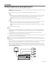
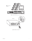
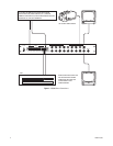
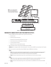
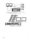
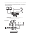
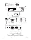
1. Make all equipment connections. Refer to Figure 1 (VS5004) or Figure 2 (VS5008).
VS5008 only:
When configured for one-monitor operation, the monitor must be connected to the MON 2 output. The MON 1 output must
be terminated with a 75-ohm BNC terminator.
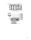
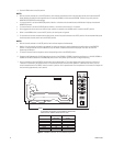
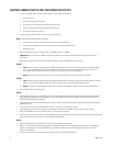
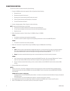
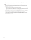
2. Make alarm connections if required. Refer to Figure 3 (VS5004) or Figure 4 (VS5008) and do the following:
VS5004
a.
Input:
Connect the alarm contact between the appropriate input (pins 1-4) and common (pin 5) on the 6-pin connector receptacle.
Pins 1 thru 4 directly correspond with the like-numbered front panel camera switches of the VS5004. The alarm output is an
open-collector NPN transistor. Current from the output to circuit ground should not exceed 600 mA.
b.
Output:
To activate an external device during an alarm, connect the device at pins 5 and 6 on the 6-pin connector.
VS5008
a.
Input:
Connect the alarm contact between the appropriate ALARM INPUT (terminals 1-8) and common (COM) terminal. The alarm
output is an open-collector NPN transistor. Current from the output to circuit ground should not exceed 40 mA.
b.
Output:
To activate an external device during an alarm, connect the device at the ALARM OUT terminal and the common (COM)
terminal.
3. Set the ALARM switch to the ON position.
NOTES:
• When an alarm occurs, the monitor immediately switches to the alarmed channel, and the associated LED blinks. Multiple alarmed
channels sequence every five seconds (VS5004) or three seconds (VS5008). The alarm has priority over the MONITOR/AUTO/BYPASS
switch settings.
• Once triggered, the alarm remains on until the input condition is removed or the ALARM switch is moved to the OFF position.
• When the ALARM switch is set to the OFF position, all alarm inputs are ignored.
4. For channels with cameras connected to the video inputs, set the front panel switches to the AUTO position. All unconnected video inputs
should have their channel switches set to the BYPASS position.
NOTE:
All channels with a switch in the AUTO position will automatically sequence through the monitor. To view one specific channel
continuously, set the corresponding switch to the MONITOR position. To remove a channel from the sequence, set the corresponding switch to
the BYPASS position.
5. Connect the AC adapter to the 12 VAC input plug on the rear of the VS5004 or VS5008. Connect the transformer to a 120 VAC (VS5004 or
VS5008) or 230 VAC (VS5004/220 or VS5008/220) power source. After power up, the switcher will begin sequencing.
6. Using a screwdriver, adjust the DWELL interval control to the desired setting. This control adjusts the interval time from a minimum of
1 second to a maximum of 70 seconds nominal. To increase the interval, turn the control clockwise. To decrease the interval, turn the
control counterclockwise. The DWELL interval control is a precision 15-turn potentiometer. Each complete turn of this control will adjust the
time interval by approximately 4 to 5 seconds.
Figure 1.
VS5004 Terminated Camera Inputs - One Monitor
MON 1
MON 2
4321
ALARM
12 VAC
INPUT
IN 1 2 3 4
OUT 6
COMMON 5
BRIGHTCONTRAST
MON 1