


C808M-G (4/05) 9
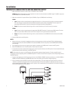
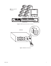
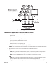
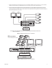
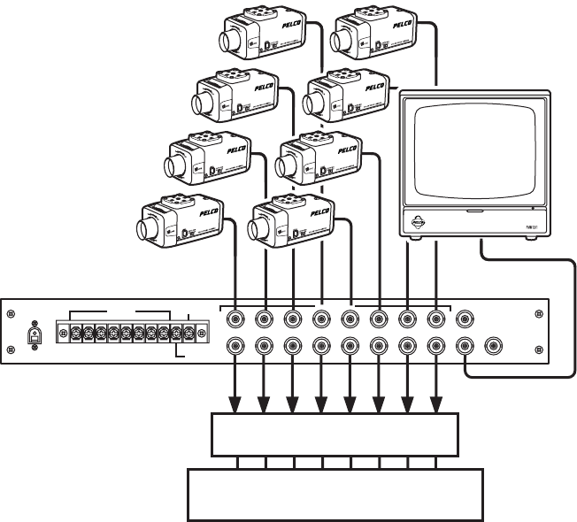
Figure 7.
VS5008 Looping Camera Inputs - One Monitor
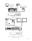
TERMINATED CAMERA INPUTS AND TWO MONITOR OUTPUTS
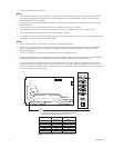
1. Convert the VS5004 to dual-monitor operation. Refer to Figure 8 and do the following:
a. Remove the cover.
b. Remove the rear panel of the chassis.
c. Remove the four screws attaching the PC board to the chassis.
d. Pull the PC board and rear panel assembly out of the chassis.
e. Turn the PC board over and rewire.
f. Replace the PC board, rear panel assembly, and cover.
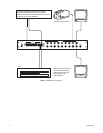
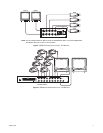
2. Make all equipment connections. Refer to Figure 9 (VS5004) or Figure 10 (VS5008).
VS5004 only:
In this configuration, MON 1 must be terminated with a 75-ohm terminator and MON 2 must be terminated in the HI Z position.
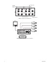
3. Make alarm connections if required. Refer to Figure 3 (VS5004) or Figure 4 (VS5008) and do the following:
VS5004
a.
Input:
Connect the alarm contact between the appropriate input (pins 1-4) and common (pin 5) on the 6-pin connector receptacle.
Pins 1 thru 4 correspond directly with the like-numbered front panel camera switches of the VS5004. The alarm output is an
open-collector NPN transistor. Current from the output to circuit ground should not exceed 600 mA.
b.
Output:
To activate an external device during an alarm, connect the device at pins 5 and 6 on the 6-pin connector.
VS5008
a.
Input:
Connect the alarm contact between the appropriate ALARM INPUT (terminals 1-8) and common (COM) terminal. The alarm
output is an open-collector NPN transistor. Current from the output to circuit ground should not exceed 40 mA.
b.
Output:
To activate an external device during an alarm, connect the device at the ALARM OUT terminal and the common (COM)
terminal.
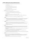
VIDEO INPUTS
ADDITIONAL EQUIPMENT
TERMINATED
VS5008 (REAR)
MON 1
MON 2 MON X
CAMERAS
87654321
12 VAC
INPUT
ALARM
INPUT
COM
ALARM OUT
12345678
NOTE: IN THIS CONFIGURATION,
MON 1 MUST BE TERMINATED
AND THE UNIT MUST BE MODIFIED
TO BE LOOPING (REFER TO FIGURE 5).