4 C1988M-B-ML (3/05)
ENGLISH
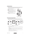
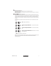
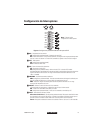
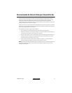
Camera Layout
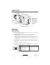
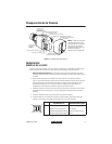
Figure 1.
Camera Layout
Installation
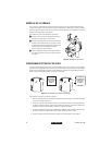
LENS MOUNTING
The camera can use a fixed iris, manual iris or auto iris lens. The camera is factory set for a CS-mount
lens, but is easily adjusted for a C-mount lens.
1.
C-Mount Lens Only -
Rotate the back focus adjustment fully counterclockwise before
installing the C-mount lens (refer to the section on
Back Focus Adjustment
).
2. Remove the cosmetic trim ring from the back of the camera (refer to Figure 1). Set the lens
mode selector switch on the side of the camera to AIV (auto iris video drive lens) or AID (auto
iris DC drive lens). Refer to the
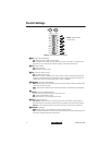
Switch Settings
section. Switch setting is determined by the
type of lens used.
3. Screw the lens onto the lens mount. Be careful to prevent dust from entering the space
between the lens and the CCD element. If necessary, use clean, compressed air to remove any
foreign matter.
4. Thread the lens cable through the cosmetic trim ring.
5. Connect the auto iris lens to the four-pin connector located on the side of the camera.
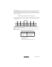
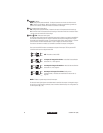
Pin connections for the iris drive connector are as follows:
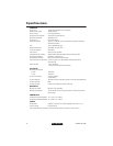
Figure 2.
Lens Connections
PIN DC (AID) AUTO IRIS LENS VIDEO (AIV) AUTO IRIS LENS
1 Control coil negative (-) Lens positive supply
2 Control coil positive (+) Not used
3 Drive coil positive (+) Video drive signal
4 Drive coil negative (-) Ground
BACK FOCUS
ADJUSTMENT
RING
BNC VIDEO CONNECTOR
LENS CONNECTOR
LED
MOUNT ADAPTER
PHASE ADJUSTMENT
LENS LEVEL ADJUSTMENT
POWER CONNECTOR
BACK FOCUS
ADJUSTMENT
LOCKING
SCREW
COSMETIC TRIM
RING
DIP SWITCHES
(COVER REMOVED)
20156
NOTE: The cosmetic
trim ring conceals the
LED light for more
discreet surveillance
operations. The trim
ring also hides the
power connectors and
protects the DIP
switches.
4
2