


6 C1988M-B-ML (3/05)
ENGLISH
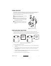
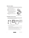
AC operation only -
If you are wiring more than one camera to the same transformer, connect one
side of the transformer to the same terminal on all cameras, and connect the other side of the
transformer to the remaining terminal on all cameras. Failure to connect all of the cameras the same
way will cause the cameras to be out of phase with each other and may produce a vertical roll when
switching between cameras.
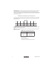
Table A.
Recommended Wire Gauge and Wiring Distances
The following are the recommended maximum distances for 24 VAC applications and are calculated
with a 10-percent voltage drop. (Ten percent is generally the maximum allowable voltage drop for
AC-powered devices.)
Wire Gauge
Example:
A camera that requires 10 vA and is installed 283 feet (86 m) from the transformer would
require a minimum wire gauge of 20 AWG.
NOTE:
Wire gauges are standard AWG or metric sizes. Distances are calculated in feet; values in
parentheses are meters.
* Minimum cable requirements:
75 ohms impedance
All-copper center conductor
All-copper braided shield with 95% braid coverage
Total 20 18 16 14 12 10
vA (0.5 mm2) (1.0 mm2) (1.5 mm2) (2.5 mm2) (4.0 mm2) (6.0 mm2)
10 283 451 716 1142 1811 2880
(86) (137) (218) (348) (551) (877)
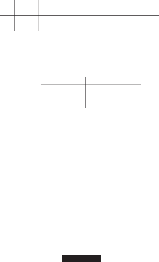
Table B.
Video Coaxial Cable Requirements
Cable Type* Maximum Distance
RG59/U 750 ft (229 m)
RG6/U 1,000 ft (305 m)
RG11/U 1,500 ft (457 m)