


C1988M-B-ML (3/05) 5
ENGLISH
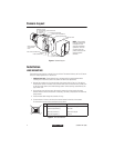
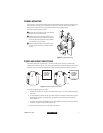
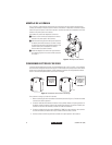
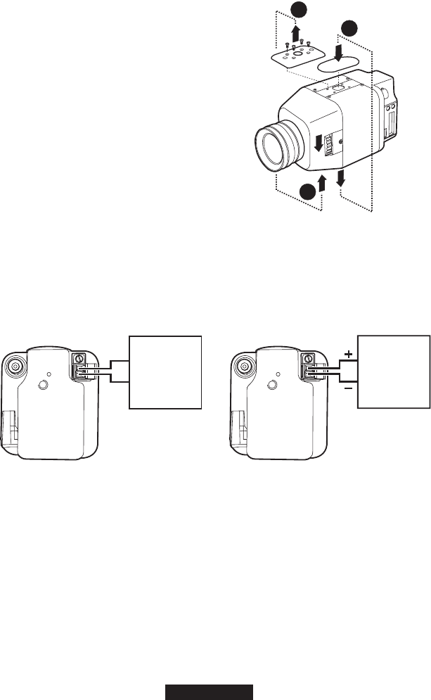
CAMERA MOUNTING
Use a standard 1/4-20 screw (provided) with a maximum thread length of 3/8-inch (10 mm) for top or
bottom camera mounting. The mount adapter may be fitted to the top or bottom of the camera.
The camera is shipped with the mount adapter located on the top of the camera.
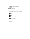
To change the mount adapter position:
ᕡ
Remove the four screws from the mount adapter
located on the top of the camera.
ᕢ
Remove the trim cover from the bottom of the
camera by prying it loose. Place the trim cover on
the top of the camera where the mount adapter
was removed. Press into place.
ᕣ
Install the mount adapter to the bottom of the
camera. Secure with the four screws removed
in step 1.
Figure 3.
Camera Mounting
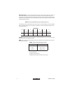
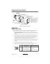
POWER AND VIDEO CONNECTIONS
The camera is designed to operate from a 12 VDC or 24 VAC power supply. The power supply
connections are shown in Figure 1. The LED on the back panel of the camera indicates that power is
connected. Use only a Class 2 isolated power supply. See
Specifications
for power consumption.
Figure 4.
Power Supply Connections
To connect the camera power and video:
1. Remove the cosmetic trim ring from the camera (refer to Figure 1). Thread cabling through the
rear cover.
2. Connect the power cable to the two-pin power connector on the back of the camera using the
terminal block connector (provided). Refer to Table A for the recommend wire gauge and
wiring distances.
3. Connect a video cable to the SIGNAL OUT connector (BNC) on the back of the camera. Refer to
Table B for the type of video coaxial cable to use.
4. Reattach the cosmetic trim ring to the back of the camera.
3
2
1
24 VAC
12 VDC
CLASS 2
ISOLATED
POWER
SUPPLY
CLASS 2
ISOLATED
POWER
SUPPLY
20155